While sketches may be the foundation of a well-designed SOLIDWORKS model, features are like the bricks and mortar. Whether you’re trying to add or remove material from your part, hollow it out, or round off the corners, there’s likely a feature (or combination thereof) that can get the job done. We will introduce you to some of the most basic and widely-used features in SOLIDWORKS, exploring their various properties and applications so you can get a head start on your next project.
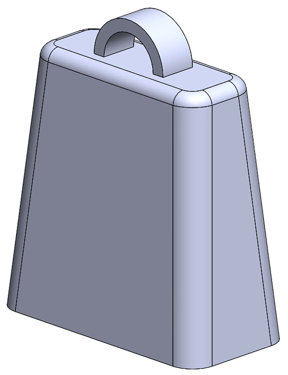
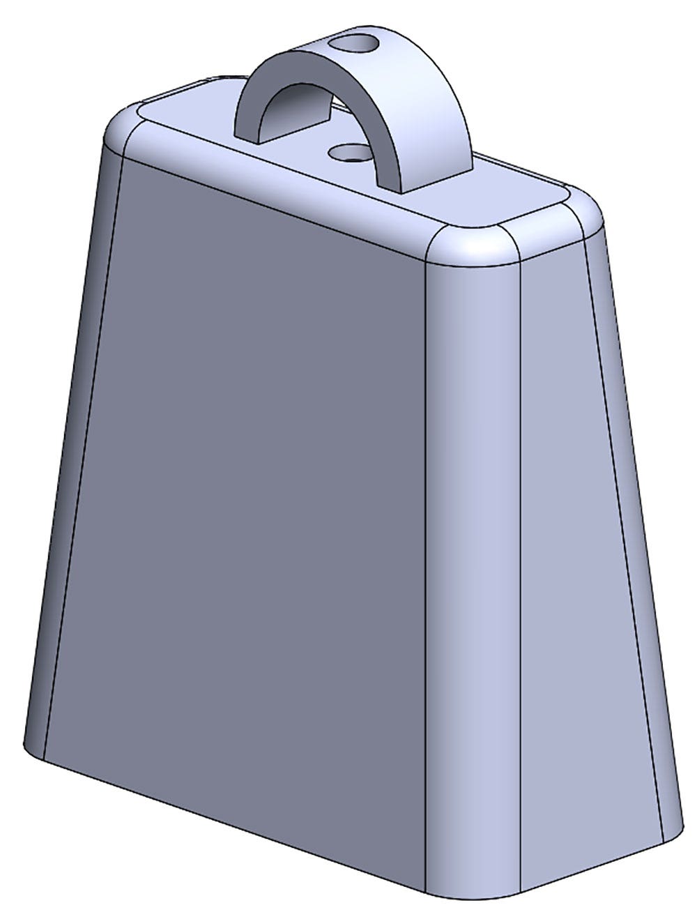
In this example, we’ll be modeling the cowbell seen below. This design requires the use of Extruded Boss, Extruded Cut, Revolved Boss, Fillet and Shell commands, which represent a few of the most common SOLIDWORKS features. While there are several combinations of features that could produce the same design, this method will give us an opportunity to explore several commands at once.
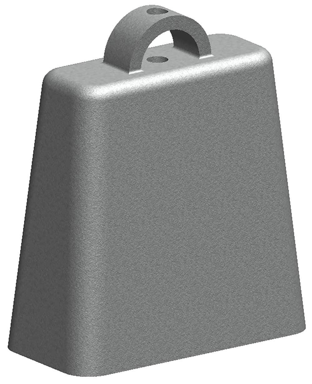
Finished Cowbell Design
Before we begin, it’s worth noting that there are two categories of features in SOLIDWORKS – sketched features and applied features. Sketched features require the use of a sketch in order to be created, and include features such as Extruded Boss/Cut, Revolved Boss/Cut and many others. Applied features do not require a sketch, and are applied directly to existing geometry. Shell and Fillet features fall into this category. If you do not know whether a feature is sketched or applied, don’t worry – attempting to create any sketched feature will prompt you for a sketch selection before allowing you to continue.
Additionally, when getting familiar with features, you’ll likely notice that many have similar names, such as Extruded Boss and Extruded Cut. The “Extruded” portion of the feature name indicates how the feature will be created (by extruding the sketch in a straight line from the sketch plane) while the second portion of the feature name indicates whether material will be added (Boss) or removed (Cut). The setup and available properties for both of these commands are nearly identical, with the only difference being whether material is added or removed.
Remember, you can search for commands by setting the search bar in the upper right of the user interface to Commands and typing in the desired command/feature.
Extruded Boss Feature
The Extruded Boss is the most basic of all SOLIDWORKS features, and extrudes a sketch along a straight line path to add material. As a sketched feature, it requires a sketch before use. The sketch below was created on the Top Plane with a Center Rectangle, centered on the origin, and fully defined with the dimensions shown. Create this sketch before continuing:
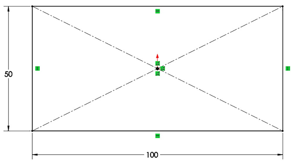
Center Rectangle Sketch for Boss Extrude
Once the sketch has been created, exit the sketch and select the Features tab of the CommandManager. Then, click the Extruded Boss/Base command. If a yellow dialog box appears in the PropertyManager asking you to create a new sketch, don’t worry – simply click on the sketch in the graphics area to use it for the feature.
The PropertyManager for the Extruded Boss allows you to control starting location, extrude depth and draft for the feature, among several other parameters:
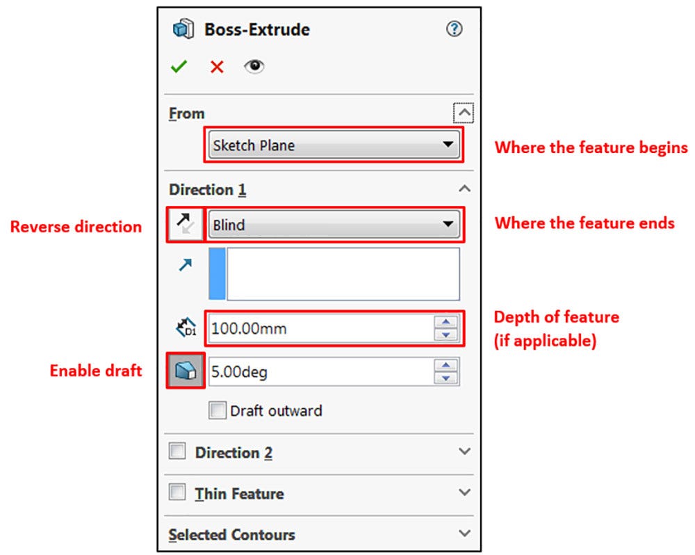
Extruded Boss/Base PropertyManager
If any of these options do not appear in your PropertyManager, make sure that the group boxes are expanded by clicking the down-arrow at the far right of the category name.
The From group box at the top of the PropertyManager allows you to select where the feature will begin adding material. This is typically kept at the default Sketch Plane option, meaning material will start being added at the sketch location. Other options in this category include starting from a specified surface/face/plane, a specified vertex, or simply at an offset distance from the original sketch. Keep this selection at the default Sketch Plane option.
The Direction 1 group box controls the depth and direction of the Extruded Boss, and includes a variety of what are known as end conditions. The default end condition is Blind, and provides an input box for feature depth. Other end conditions allow for a feature to extrude all the way through the geometric limits of the model (Through All), to extrude up to a specific surface, vertex, or body, or to extrude equally in opposite directions (Mid Plane). Many of these end conditions are available in other features as well.
Additionally, the Reverse Direction button can be toggled to flip the direction of the feature, and the Draft On/Off button will apply draft to the feature, making the profile smaller as it continues along the extrude path. Finally, the blue box allows for the selection of a direction reference (usually a sketched line or a model edge) to change the default direction of the extrude.
Ensure that the end condition for the feature is set to Blind, and input a depth of 100mm. Additionally, use the Draft On/Off button to toggle draft, and input a value of 5 degrees. This will narrow the profile along the path of the extrusion. Leave all other properties at the default setting. Your PropertyManager should look similar to Figure 3. Once finished, click the green check mark to complete the feature:
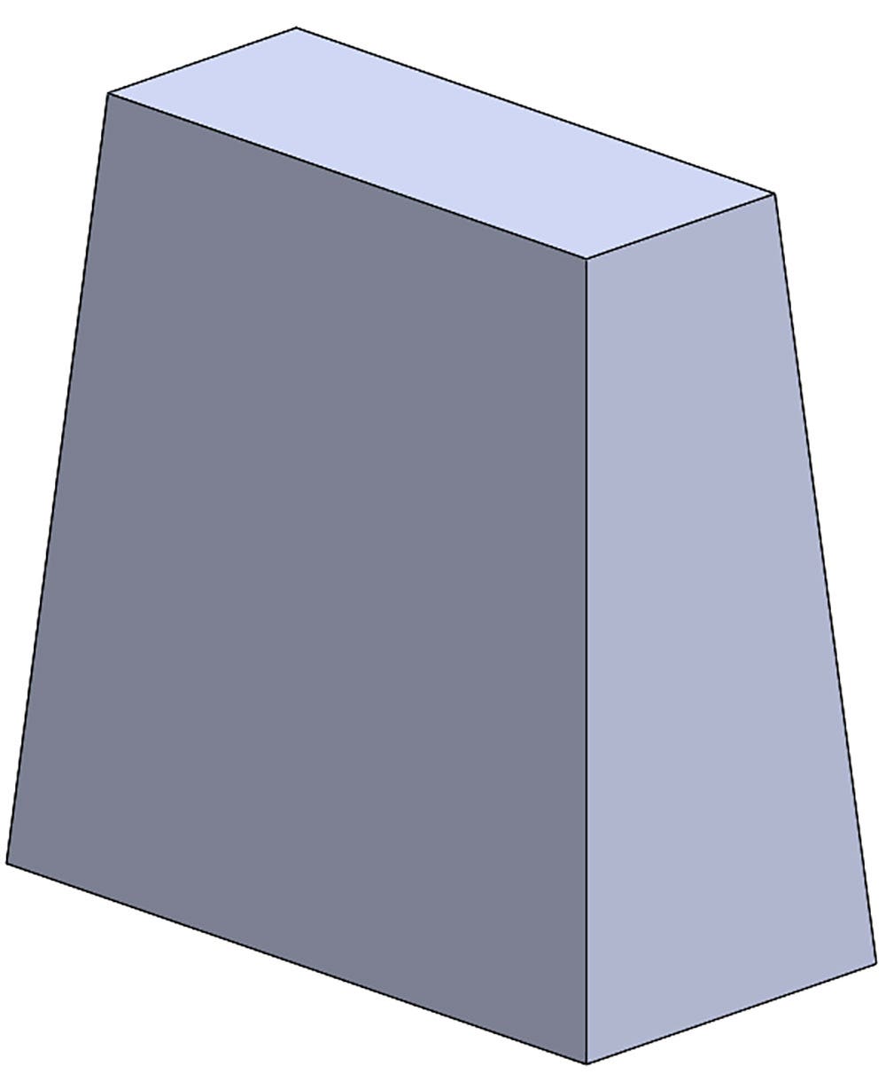
Extruded Boss Feature
Fillet Features
Fillets are classified as applied features, and as such do not require a sketch to be used. Fillets serve to round off edges and/or corners by adding or removing material, depending on whether the edge is internal or external. It should be noted that fillets of different sizes must be created as separate features. Typically, it is best practice to create the largest fillets first, and follow with smaller fillets.
To achieve the rounded shape for the cowbell, we’ll add two sets of fillets. Click the Fillet command in the Features tab of the CommandManager. Once the PropertyManager appears, you can begin selecting edges and/or faces to specify where the fillets should be added. Selecting an edge will add a fillet to that edge only (and all edges tangent to the selected edge, by default). Selecting a face will add a fillet to every edge of the selected face. If you make a mistake during selection, simply click the incorrect edge/face a second time to deselect it.
Before beginning, ensure that you are in Manual mode by clicking Manual at the top of the PropertyManager. For more information on using the FilletXpert mode, please see this video. You’ll also want to make sure that you’re creating a Constant Size Fillet by clicking the first icon in the Fillet Type group box if it’s not already selected.
Begin by selecting all four long edges, one on each corner of the part. Once the edges have been selected, a yellow preview will appear indicating what the fillets will look like. In the Fillet Parameters group box, be on the lookout for an input box to set the fillet size. Adjusting this value will update the preview, allowing you to investigate different options before confirming. Set the fillet size to 10mm, and click the green check mark to complete the feature. Your PropertyManager and part should look similar to those shown below:
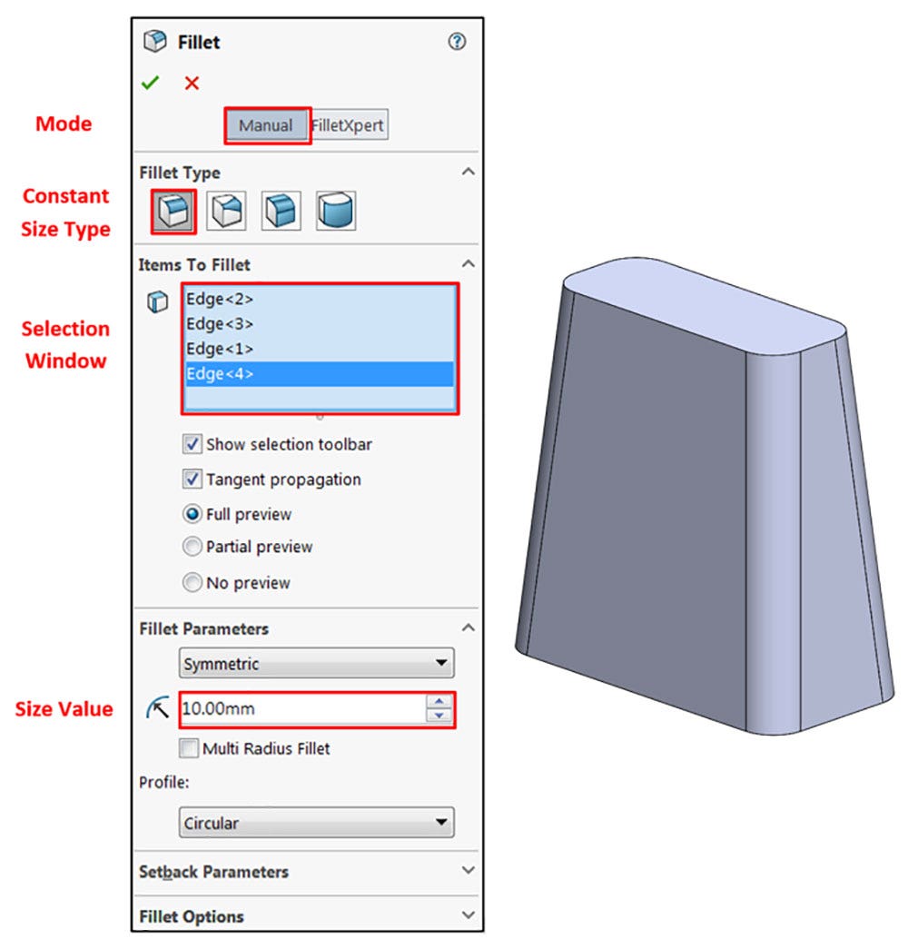
Fillet PropertyManager and Cowbell Design After First Fillet
To create the second fillet, repeat the process above to start a new Fillet command. This time, however, select the entire top face of the part to automatically select all the edges of the face. Additionally, set the fillet size to 5mm before confirming. If completed correctly, your model should look as shown below:
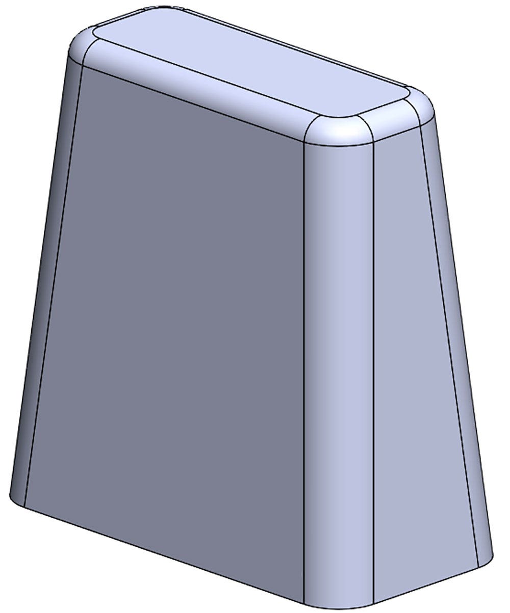
Cowbell Design After Second Fillet
If you ever make a mistake or need to edit a feature for any reason, simply locate it in the FeatureManager Design Tree, right click it, and use the first icon in the top portion of menu that appears (known as the context menu). This will take you back to the PropertyManager you initially used to define the feature, and any adjustments can be made as needed.
Shell Feature
For the cowbell to function properly, the inside needs to be hollowed out and the bottom must be open. While this can technically be done with a well-crafted Extruded Cut, it’s much simpler in many cases to take advantage of the Shell command, which is another applied feature. The Shell command allows you to define a wall thickness and automatically hollow the part, while allowing faces to be removed as needed. If no faces are specified to be removed during a Shell feature, the part will be hollow, but this can only be seen by creating a cross section of the part.
Access the Features tab of the CommandManager and activate the Shell command. The PropertyManager for the Shell is very simple – the first input box allows the wall thickness to be specified. Set this value to 2.5mm. The blue selection box allows specified faces to be removed from the model. In this case, since we want the bottom of the bell to be open, click in this selection window and then select the bottom face of the part.
The remaining options in the PropertyManager are useful for creating a Shell with different thicknesses in different areas of the part, but will not be used here. Finally, confirm the command and evaluate the results. The PropertyManager and resulting part after creating the Shell feature are shown below:
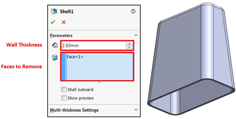
Shell PropertyManager and Resulting Part
Revolved Boss Feature
Our next design feature will be a loop for the top of the bell. It’s important that this feature be created after the Shell feature to ensure that the handle is not hollowed out. It will be created through the use of a Revolved Boss feature, which adds material by revolving a sketch around an axis. Remember, once geometry has been created in your model, any flat face can be used as a sketching surface. In this case, begin a sketch on the top face of the bell and create the sketch shown below. The rectangular portion was constructed from a Center Rectangle with the dimensions shown, and a horizontal relation between the center point and the origin:
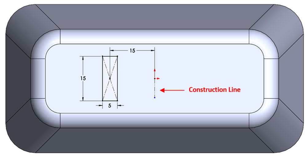
Sketch for Revolved Boss Feature
It is also very important to include the vertical construction line from the origin, as it will serve as the axis that the feature is revolved around. To create a construction line, use the dropdown arrow next to the line command in the CommandManager and choose the Centerline tool. The direction (up or down from the origin) and length are not important. Construction geometry can be used for a number of different operations, but is not factored into the profile of a feature.
It should also be noted that sketch dimensions are not restricted to the sketch itself; it is very common to apply a dimension between a sketch entity and a model edge, for example.
Once the sketch has been completed, exit the sketch and activate the Revolved Boss command from the Features tab of the CommandManager. The PropertyManager that appears has many similar elements to the Extruded Boss, with a couple key differences:
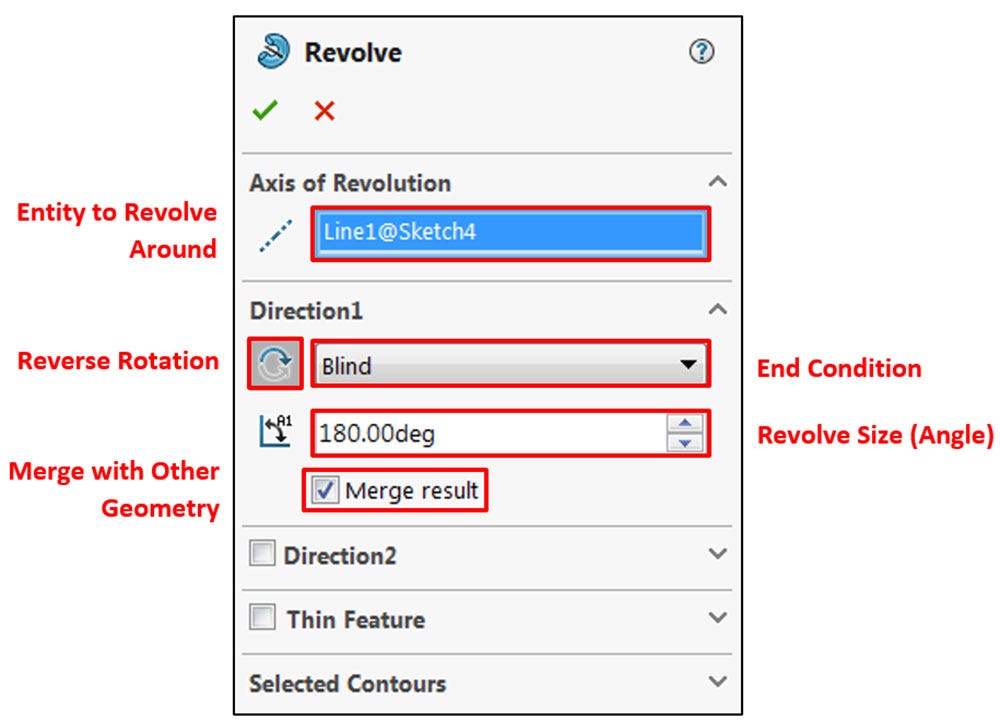
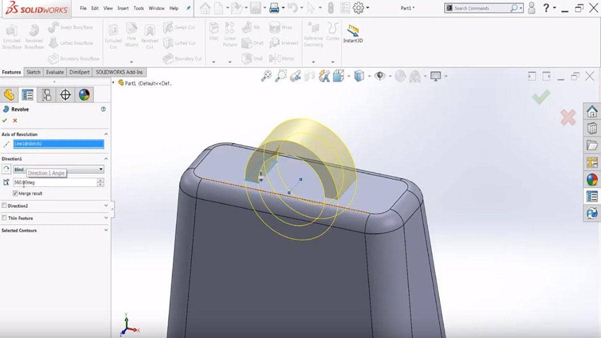
Revolved Boss PropertyManager
The first input box allows for the selection of an axis to revolve the sketch around to create the feature. This selection is most commonly a sketched line segment, but other selections such as linear model edges can be used here as well. In this example, we’ll use the vertical centerline that was previously sketched. If there is only one construction line in your design, it will automatically be selected as the axis of revolution; if not, click the sketched centerline to use it as the axis of revolution.
It is important to note that the first selection made in this PropertyManager is the axis of revolution, and not the profile to be revolved. This means that if the Revolved Boss command is initiated without the sketch preselected, selecting a portion of the sketch graphically will use that sketch segment as the axis of revolution, and the resulting preview may not reflect the feature you’re trying to create.
The easiest way to avoid this potentially confusing behavior is to ensure that the sketch is preselected prior to starting the command by clicking the sketch in the FeatureManager. Alternatively, if you do not preselect the sketch, make sure to select the axis of revolution when selecting the sketch graphically. If you find yourself with an improper preview, simply right click the Axis of Revolution selection box and delete the selection. Then, select the appropriate axis. One possible improper selection is described below, followed by the appropriate selection:
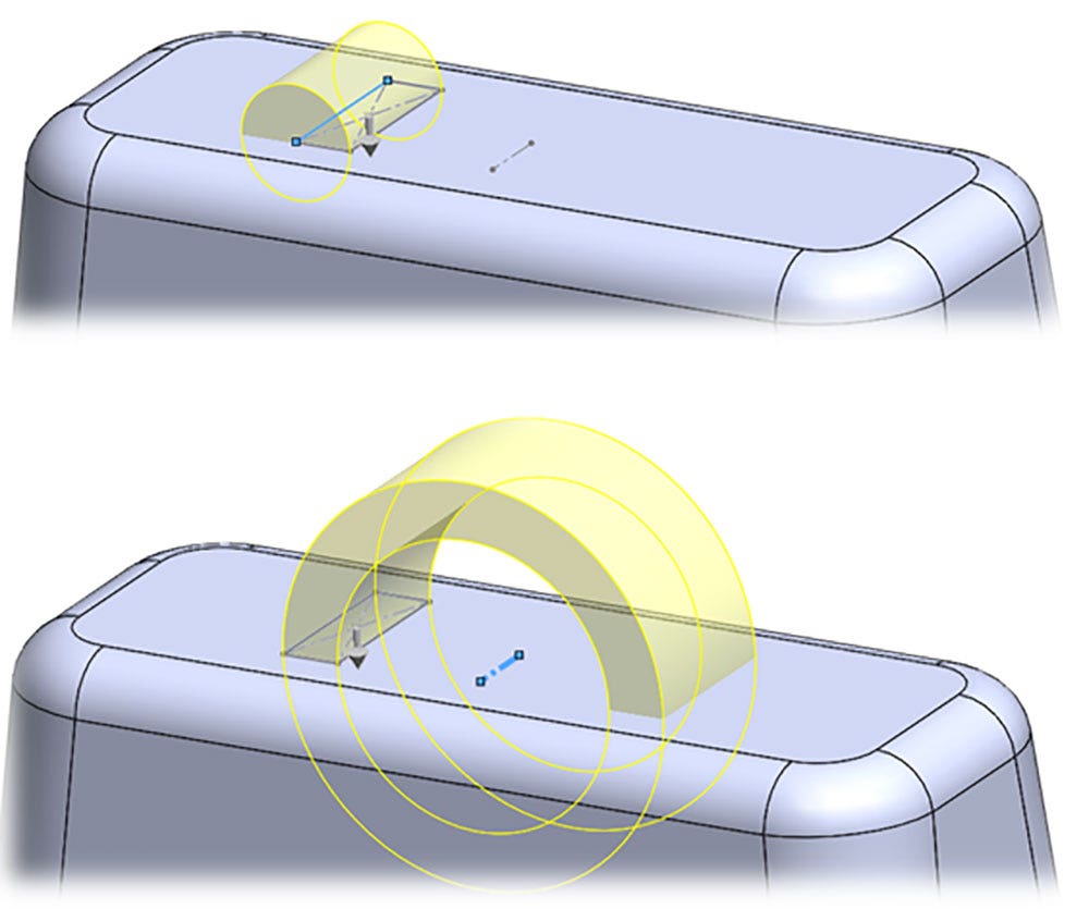
Improper Axis of Revolution (Top); Proper Axis of Revolution (Bottom)
Even with the correct axis of revolution, you’ll find that by default the feature completes a full rotation all the way through the model. To avoid adding material to the inside of the model, set the Direction 1 Angle to 180 degrees. If necessary, use the Reverse Direction button to ensure that the material is added to the top of the design rather than the bottom. Leave all other options at the default values.
One more important aspect to note is the presence of the Merge Result option. This important option is selected by default, and ensures that the feature will be combined with existing geometry, rather than being created as a separate body. Outside of advanced techniques, this option should be left on, and will only appear for features that add material.
The completed Revolved Boss feature is shown below:
Completed Revolved Boss Feature
Extruded Cut Feature
The final feature for this design will be a circular cut, extending through the entire model at the center for the attachment of a handle and the clapper for the bell. Use the default Top Plane to sketch a circle centered on the origin with a 7.5mm diameter dimension. Remember, since this is not the first sketch of the design, the default planes will not appear when starting a new sketch, and cannot be selected graphically. Instead, you will have to manually create the sketch by right-clicking the Top Plane in the FeatureManager and clicking the Sketch command in the context menu.
Alternatively, the FeatureManager flyout window can be used. When prompted for a plane/face selection after using the Sketch command from the CommandManager, click the small arrow at the top left of the graphics area (followed by the part name). This will show the FeatureManager inside the graphics area, where the Top Plane may be selected.
This technique is also very useful when you need to see the FeatureManager and a PropertyManager at the same time:
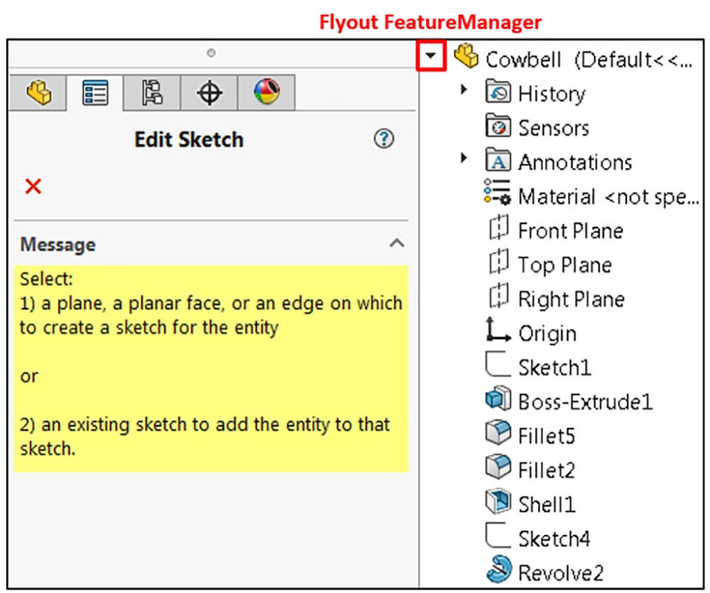
Leveraging the Flyout FeatureManager
The completed sketch for the circular Extruded Cut is shown below:
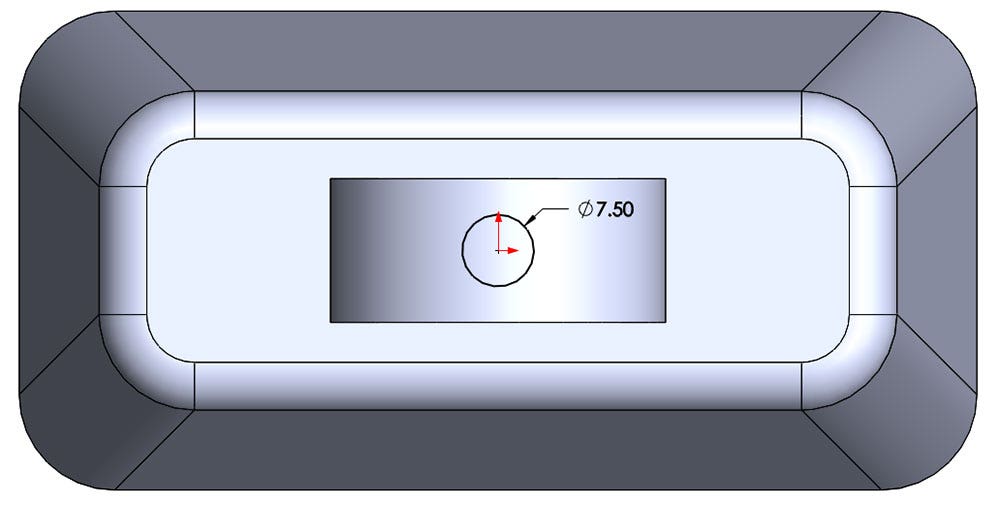
Circular Sketch for Extruded Cut
Remember, even though it appears that the circle is being sketched on the top of the design, this is only a matter of perspective. Rotating the view will reveal that the sketch actually exists near the bottom of the part. Even when looking from an isometric perspective, sketches are locked to orientation of the plane on which they were created. Sometimes, it will be necessary to rotate the view while sketching to capture the appropriate sketch relations or dimensions.
Once completed, exit the sketch and activate the Extruded Cut command from the Features tab of the CommandManager. You may need to rotate the view to see the preview properly. Ensure that the direction of the cut is set to go upward by using the Reverse Direction button if necessary, and then change the end condition of the feature from Blind to Through All. This will ensure that even if the design changes size in the future, the cut will always continue all the way through the model. Leave all other options at default, and confirm the command.
The completed model is shown below:
Completed Cowbell Design
Remember, should you ever need to make changes to your design, features can be edited at any time by right-clicking them in the FeatureManager and using the Edit Feature command in the context menu. Typically, features are edited when depth or end conditions need to be adjusted; if the actual shape (or profile) of a feature needs to be changed, you will likely need to edit the underlying sketch instead. Additionally, thinking ahead when editing features near the top of the Design Tree is very important, as these changes can have downstream effects that may break other features.
SOLIDWORKS Features Tutorial
Don’t forget, the built-in tutorials in SOLIDWORKS can be of great assistance for getting familiar with new tools and techniques, and the online Help File is an excellent learning resource. Visit our website to learn more about SOLIDWORKS CAD, or contact us at Hawk Ridge Systems today. Thanks for reading!


