In this post, we’ll cover how to arrange assets in a facility using magnetic mates. Magnetic mates allow assets like robot cells, equipment, and fixtures to be quickly and easily laid out on a factory floor and just as quickly rearranged.
Facility Layout is a powerful assembly technique that can be used in SOLIDWORKS to help streamline the arrangement of machinery or equipment on a factory floor. There are two stages to using the technique, first, normal SOLIDWORKS models (these can be parts or assemblies that represent the machinery or equipment) must be turned into assets.
In the first part of this blog series, an asset was published from a model of a cabinet. Once the assets have been made, they can be inserted into the facility assembly. In this article, we’ll insert the asset into a facility assembly and mate it with other assets.
Preparing the Facility Assembly
First, before any assets can be inserted, a ground plane must be defined for the facility assembly. This can be a new assembly or an existing one. To define a ground plane, go to Insert > Reference Geometry > Ground Plane from within the assembly file.
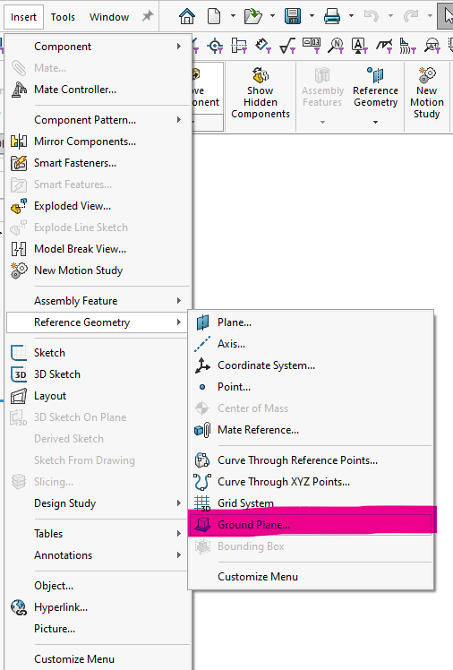
Select an appropriate plane to use, (the top plane is often a good choice), then click the green checkmark. A folder will appear in the assembly tree called ground planes, under which will be the ground plane you just created.
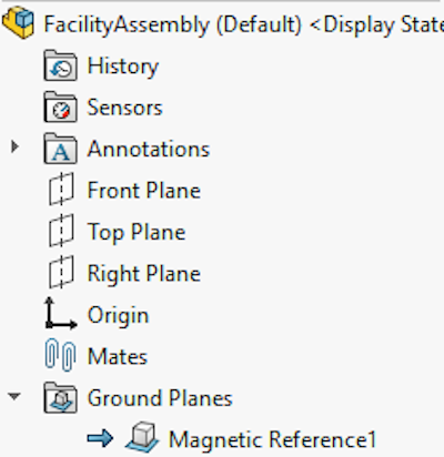
Multiple ground planes can be defined like the main floor, a mezzanine, walls, ceiling, etc. In the event of multiple ground planes, only one can be active at a time. Double-click on the desired ground plane from within the tree to make it active.
Inserting Assets
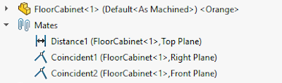
Inserting assets works just the same as inserting normal components in normal assemblies. The cabinet model from the previous blog will be inserted here. It automatically attaches to the (active) ground plane of the assembly. Two more mates will be added manually to make the cabinet coincident with the front and right planes of the assembly. The distance mate gets formed automatically thanks to the ground plane and published reference of the cabinet. The coincident mates need to be made manually.
Magnetic Mates
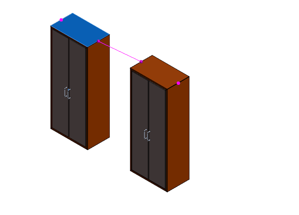
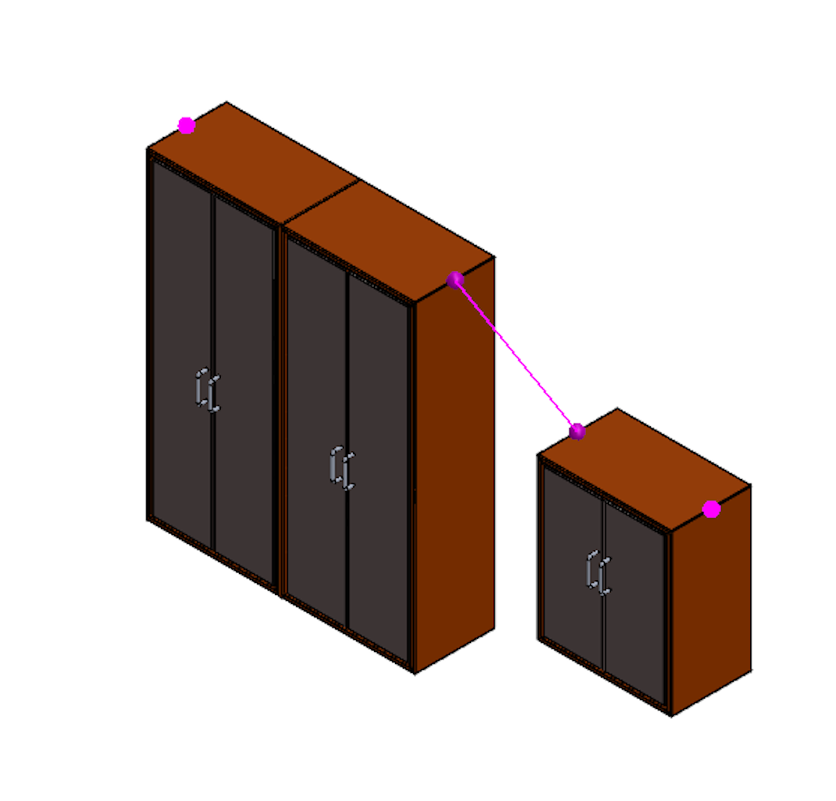
The real power of Facility Layout comes when more assets are added. When a second cabinet is inserted into the assembly, the connectors defined in the asset publisher will attempt to snap to each other, showing a purple line between nearby connectors.
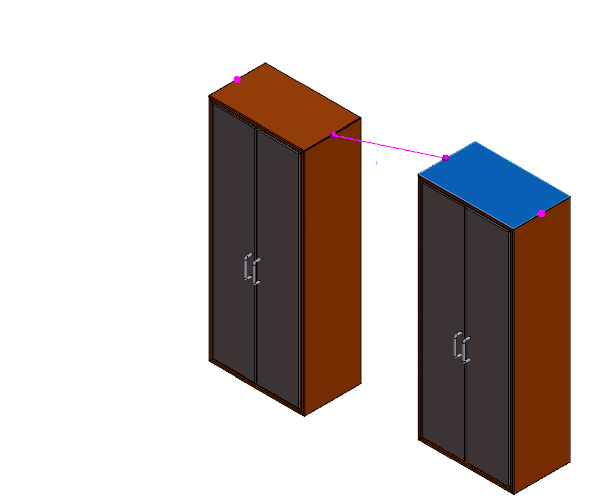
By moving the asset to various locations in the assembly, different connector combinations will activate, hence the name magnetic mates.
While the magnetic mates will automatically change depending on the position of the assets, the connectors can also be manually cycled using the left ‘[‘ and right ‘]’ bracket keys on the keyboard.
The right bracket key ‘[‘ cycles the connectors on the static component. The left bracket key ‘[‘ cycles the connectors on the moving component.
This can be helpful for assets with many connectors in a small area. Once the desired magnetic mate is shown on the screen, simply click to place the asset and it will snap into place.
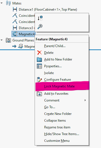
To move existing assets, click and drag. The asset will automatically break its magnetic mate and start showing previews to other magnetic mates nearby (manually created mates will stay intact.) To prevent this movement, right-click on the magnetic mate from the tree and choose “Lock Magnetic Mate”.
One last note on magnetic mates, when connectors are at different heights above the ground, the ground plane takes priority over the connector height. This results in the magnetic mate effectively forming between the projections of the connectors onto the ground plane without regard to their height.
Conclusion
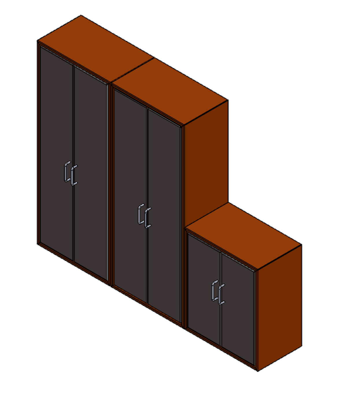
Now that you know how to insert and arrange assets in a facility using magnetic mates, you can use them to lay out robot cells, equipment, and fixtures quickly and easily. Combined with the previous article on how to create assets this should cover the basics of getting started with facility layout in SOLIDWORKS.
Have more questions or need help with your facility layout workflows? Get in touch with Hawk Ridge Systems today.