Gusset and End Cap tools in SOLIDWORKS Weldments significantly enhances your ability to create precise and robust welded structures. In this article, we will explore the robust capabilities of SOLIDWORKS Weldments, a versatile toolset for the efficient, simple creation of welded structures. Specifically, we will look at how to effectively use the Gusset and End Cap tools. By the end of this article, you should have a comprehensive understanding of how to incorporate these two commands into your own designs.
*There is also a Gusset tool that is used in SOLIDWORKS Sheet Metal, note that this is a separate tool not discussed in this article.
Gussets
Gussets are common features in framed structures to add strength and rigidity to corners. In SOLIDWORKS, the Gusset tool can create a triangular or polygonal gusset between two structural members.
Command Location: Weldments Tab > Gusset
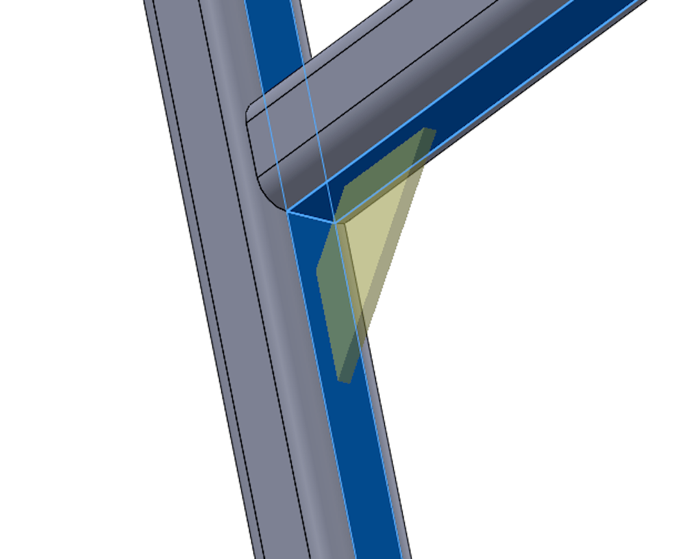
To add a gusset to this corner, first select two faces. The faces must be planar and intersect at a corner. Here the corner is perpendicular, but gussets can also be added to corners of any angle.
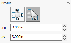
Then, select whether a triangular or polygonal gusset is desired. The dimension fields below will change depending on the profile type.
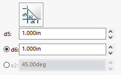
Regardless of the profile type, there is also an option to add a chamfer to the inside corner of the gusset. This can be useful to allow room for a weld bead.
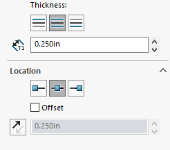
Finally, there are options to alter the gusset’s thickness and location. If the gusset is being made manually with an extrude feature, location can be thought of as the sketch plane, while thickness can be thought of as the direction of extrusion: forward, backward, or midplane.
While there are technically 9 different combinations here (3×3), they are commonly adjusted together. E.g. if the left thickness option is used, the left location option will also be used. There is also an option to add a manual offset distance if further control is required.
Keep in mind that only one gusset can be created at a time; you must complete the command and reactivate it between subsequent gussets. Gusset parameters will be preserved from the last gusset created each time the tool is launched. If you have many gussets, consider using the pin button on the Property Manager to keep the command open between subsequent gussets, or taking advantage of symmetry with patterns and mirrors.
End Caps
The End Cap command can be used to close off the ends of structural members with closed profiles. They do not work on open profiles like angle, c-channel, or I-Beam. They represent a flat plate or sheet being welded across the opening of a tubing profile.
Command Location: Weldments Tab > End Cap
To create an end cap, first select a flat profile face at the end of a structural member. Multiple faces can be selected at once to create multiple end caps in a single feature.
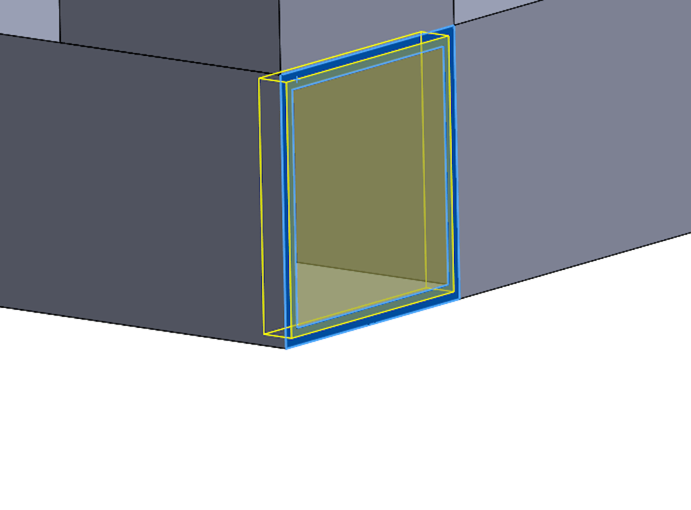
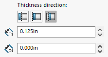
The thickness value is entered, and then one of three options can be chosen for the thickness direction.
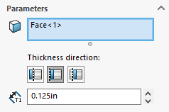
Outward leaves the tube as-is and adds the end cap on top of the tube, increasing the overall length.
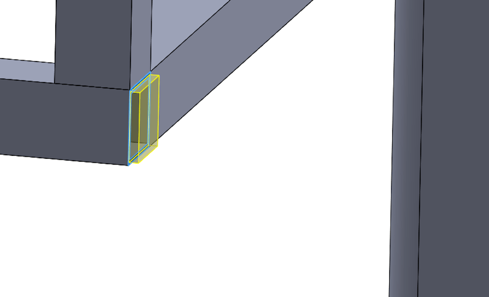
Inward shortens the tube by the thickness of the end cap first, maintaining the same overall length. This can be helpful for preserving clearances to nearby parts while being simpler to weld than an internal cap.
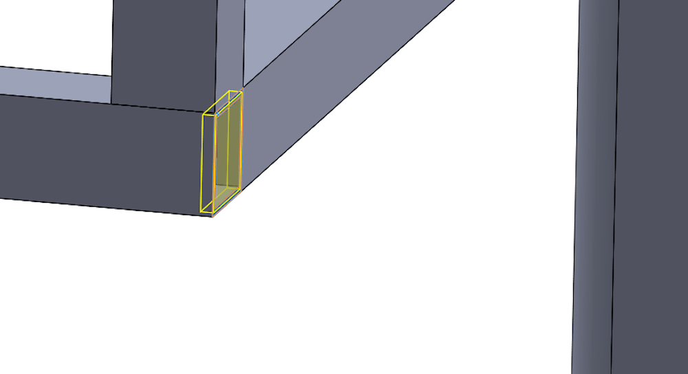
Internal leaves the tube as-is, but places the end cap inside the tube, maintaining the same overall length. Another dimension will become available when using this option which controls the inset distance of the cap. A value of 0 will make the cap flush with the end of the member. When using the internal option, the offset in the next section will automatically be changed to refer to the internal dimensions of the structural member, rather than the external dimensions.
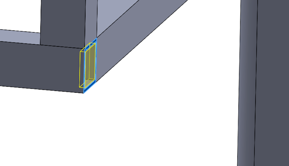
The next section is offset; this value controls how much smaller the end cap will be than the member. The arrow button can be used to make the end cap larger than the member, which is potentially useful to create feet at the base of tubes. This offset can be defined either as an absolute measurement or as a ratio of the wall thickness. In this example, a thickness ratio of 0.5 is used. Because the tubing has a wall thickness of 0.065”, the cap will have a clearance of 0.0325” on all sides of the tube.

Finally, a corner treatment can automatically be applied to any sharp corners of the end cap if desired. Users can choose between a fillet or a chamfer. If no corner treatment is desired, the box can be left unchecked.

Ready to Learn More About Gusset and End Cap Tools in SOLIDWORKS Weldments?
Hopefully you now have a good understanding of Gusset and End Cap tools in SOLIDWORKS Weldments. If you can effectively utilize these features, you can streamline your design process, improve the robustness of your model, and save valuable time.
Ready to learn more about SOLIDWORKS Weldments? Get in touch with us today.


