Customers ask me if there is a tolerance analysis tool for SolidWorks. The answer is… “There is, and you may already own it.”
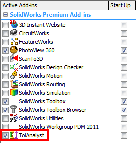
Anyone who has SolidWorks premium has an add-in call TolAnalyst that is included with this package.


This tool leverages information put in by the free DimXpert tool within SolidWorks. DimXpert for parts automatically puts in manufacturing or inspection dimensions, with tolerances, based on rules and datum you input.
The DimXpert is actually inside of all SolidWorks packages (basic, professional, and premium). The DimXpert tool is activated by clicking on the tab along the top of the feature manager as shown. There is a button to start the Auto Dimension Scheme.
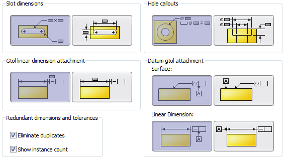
The DimXpert allows you to set up dimensioning schemes and areas to input surfaces as datum. Pick the surfaces in the order of importance: primary, secondary and tertiary will be used as A, B, and C references for Geometric Tolerances.
You also have the option to have all features in the part defined, or you can set this to selected features if you want to manually select only sections of the model.
The Feature Filter allows you to define what type of geometry you want defined.
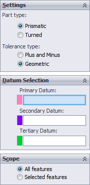
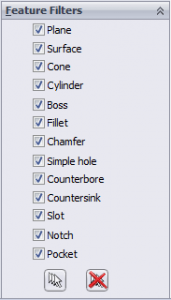
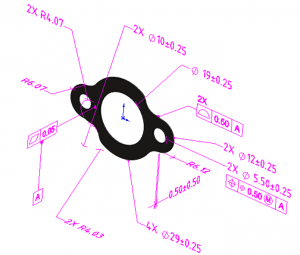
The result will be a part fully defined with dimensions and tolerances according to the requirements of ASME Y14.41-2003 and ISO 16792:2006. You can then use the tolerances with TolAnalyst to perform stack analysis on assemblies, or with downstream CAM, other tolerance analyses, or metrology applications. The control over the tolerance numbers can be found in the Tools, Options, Document Properties you can set these and save them to your part template.

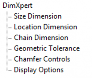
With the add-in for TolAnalyst turned on, and while in an assembly containing parts with DimXpert information you can start a stack up study. Press the DimXpert tab along the top of the assembly feature manager, then press the TolAnalyst Study button.


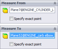
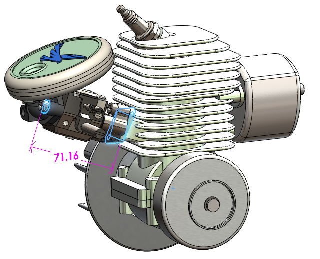
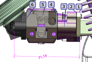
Now you can select faces on components to set up a linear dimension you wish to analyze, here I’ve selected two faces of two parts, this will show the target distance between the two. Press the blue arrow to continue the analysis.

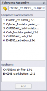
Now you can select all the components that make up the stack. Here I have six parts including the gaskets. Again the blue arrow takes us to the next step.

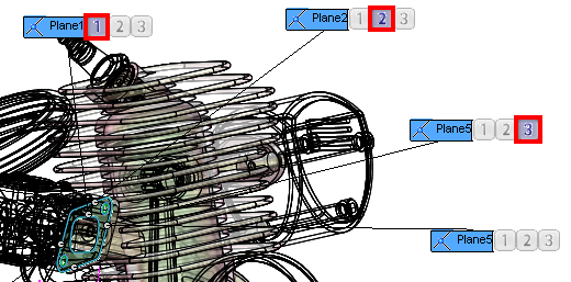
Each component in the stack has many tolerances you need to set up which tolerance is most important to study you are doing in this case I am concerned with the how the flat face of the base component matches up so I will set that to primary by picking the number 1. I can continue this, setting secondary and tertiary constraints in, much like the specification of datum in DimXpert. After I have assigned importance to the constraints in the assembly I hit the blue arrow to continue.
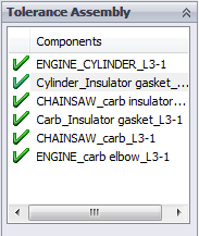

The study will now be run and you get several results:
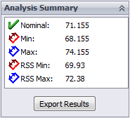
Min – This is the Least Material Conditions for all parts the worst case smallest stack.
Max – This is the Most Material Conditions for all parts the worst case largest stack.
RSS Min/Max – The Route Sum Square is a statistical method. It assumes the components will probably be within the middle of the tolerance rather than being the extreme ends of the tolerance.


