Recently, I ran into a scenario where I had to design some custom-sized gears and found a creative way to make a beveled gear that I thought I should share. There are equations to calculate specifications of the bevel like the cone angles of the gears, tooth, face width and cone distances. I wanted to use SOLIDWORKS and do as simple of calculations as possible. The first step was to get the gear ratio I wanted and for this example, it is 20/40 or 1/2.
Establishing Sketches
To start, I made two orthogonal sketches with the pitch diameter of each gear (20mm and 40mm). The 40mm circle was sketched on the top plane and the 20mm gear was sketched on a plane parallel to the right plane and tangent to the edge of the 40mm circle. The sketch with the 20mm circle had a vertical relation to the center of the bigger circle and the edges of the circles are tangent.
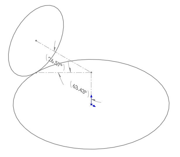
To obtain the cone angles, a sketch was created on the front plane with 3 lines creating a right-angled triangle. Each circle had a line starting at the center point and extended until it intersected the other line. A third line was then created from that intersection point to the location where to two pitch circles connected. This third line represents the meshing interface between the two gears and the smart dimension tool can be used to determine the cone angles of both the bevel gears. The figure below shows the sketch used to determine the cone angles of the bevel gears. The 20mm gear has a cone angle of 26.57 degrees and the 40mm gear 63.43 degrees.
Layout Sketch for Bevel Gear
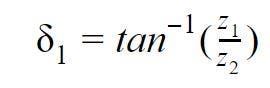
Equation One: Cone Angle Calculated Using the Gear Ratio
Equation 1 calculates the cone angle (δ) for bevel gears based on the number of teeth (z) on the two meshing gears. When we solve this equation, we obtain the same values that we measured using SOLIDWORKS.
Incorporating Sketch Blocks
For this custom gear train, I have made a series of sketch blocks for different module one gears. I used a layout model which contains equations and relations to build me any gear with the input being the number of teeth, module and pressure angle. The only manual part in that model is saving the sketch as a sketch block. I also used a design table to quickly create all the configurations I needed but I will save that story for another blog. The two sketch blocks used for these bevel gears are the 20mm and 40mm ones.
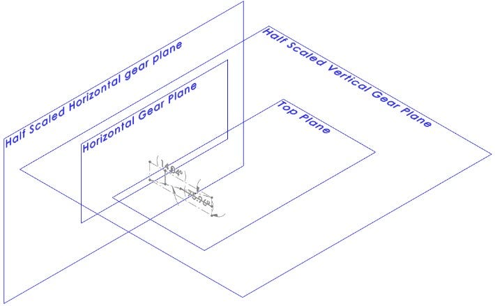
For the bevel gear, I used the full-sized sketch block and a half-sized sketch block and lofted between the two to create the gear. I just needed to figure out how far to space them apart to achieve the cone angle. I had two options for this: trigonometry and hand calculations, or let SOLIDWORKS do the work for me. The first thing I needed to do was pick a value to scale the sketch block by which was acceptable input within the block property manager. For simplicity’s sake, I am going to choose a factor of 0.5 and this means that my radius is going to be half the size.
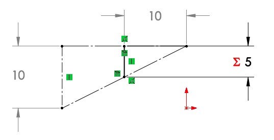
Sketch Used to Calculate the Distance of the Scaled Sketch Block
As seen above, the vertical construction line is the radius of the 20mm circle and is measured at 10mm. We want to find the horizontal distance where that vertical line is going to be half the length. To do this I made a vertical sketch line that was coincident to the cone line and centerline of the pitch circle. I then dimensioned it to be half the length of the vertical line using an equation. That information was enough to fully define the line and locate its horizontal position. I then created a reference dimension to measure the length of the adjacent side of the right-angle triangle. Since they are similar triangles, I could have just used a ratio to determine the position of the new line, but this method captures the design intent and will automatically update should I decide to change my gearing ratio.
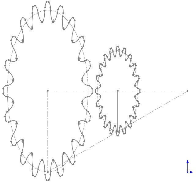
Sketch Blocks Placed Upon the Cone Line for Lofting
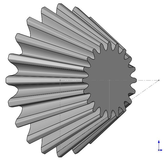
Solid Body Created by Loft
With this new line, I created a plane to put my scaled sketch block on. As you can see in the sketch picture above, the pitch circle of each of the gears lies perfectly on the cone line. This is ideal for a good mesh of the gears. These two sketches are then used to create a loft feature as seen above.
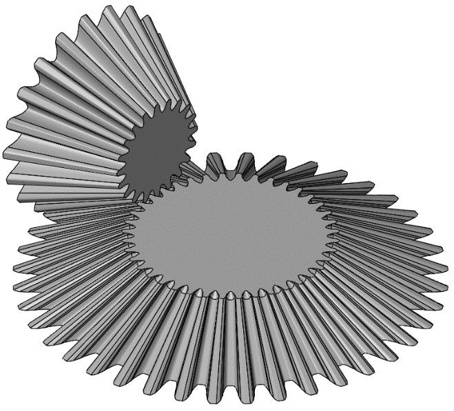
Isometric View of Bevel Gears
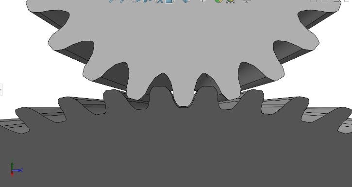
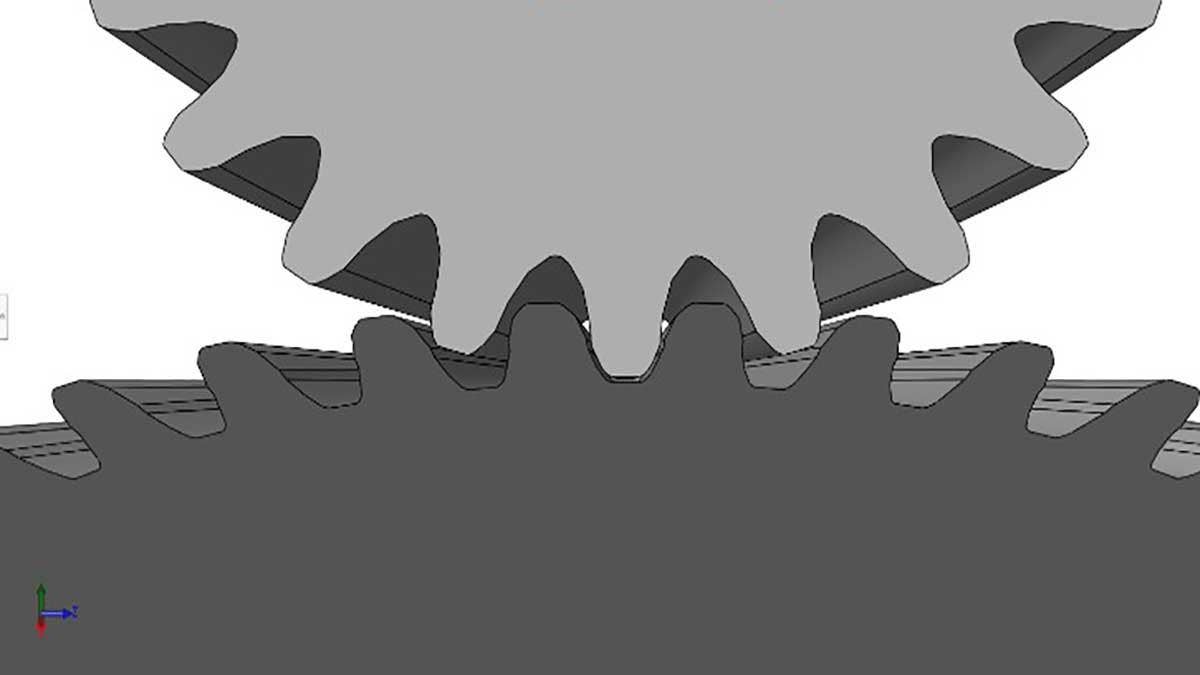
Close Up of Gear Teeth Meshing
The process was repeated for the 40mm gear to generate a pair of meshing bevel gears as seen in the figure above. The teeth initially had some multi-body interference, but the Indent tool cut away the necessary clearance in order to ensure smooth meshing. The figure above is after using the Indent tool and you can see the 0.1mm clearance that was added to ensure the gears do not bind when in operation.
Using Global Variables
This approach to creating bevel gears lets me easily get the layout for any gearing ratio with the use of global variables. All I have to do is change the global variables representing the pitch diameters, as seen below, and the automation takes me to the step of adding in the gear profile blocks. The images below are various gear ratios showing the relocating of the sketch planes and recalculation of the cone angle.
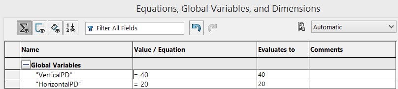
Equation Manager Displaying Global Variables Used for Automating New Designs
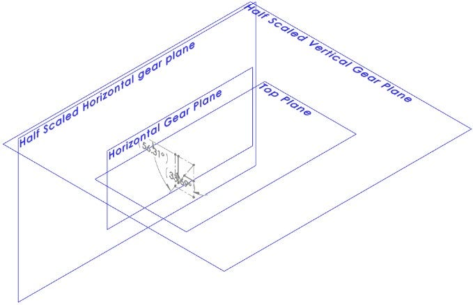
Layout With a 10mm Horizontal Pitch Diameter and 40mm Vertical Pitch Diameter
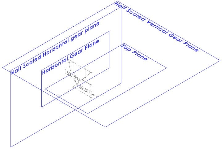
Layout With an 18mm Horizontal Pitch Diameter and 12mm Vertical Pitch Diameter
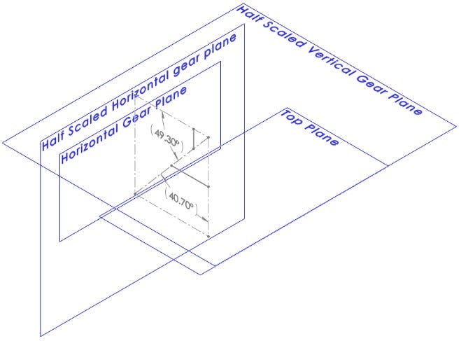
Layout With a 30mm Horizontal Pitch Diameter and 25mm Vertical Pitch Diameter
Layout With a 50mm Horizontal Pitch Diameter and 43mm Vertical Pitch Diameter
For more information on SOLIDWORKS or if you have any questions, contact us at Hawk Ridge Systems today. Thanks for reading!


