In the SOLIDWORKS assembly environment, you can visualize the center of mass (COM) in the graphics area and read the coordinate points, but you cannot reference the COM. In the part modeling environment, there is a Create Center of Mass Reference Point button that will make a selectable, relatable point at the part’s COM.
The Create Center of Mass Reference Point button is found in the popup menu after you select the center of mass feature, but only for part files. In the assembly environment, that capability is nonexistent. The Center of Mass Reference Point is a time-dependent feature (static location in the Feature Tree), so no cyclical references can be made. Imagine adding material that is offset from the COM, causing the COM to relocate causing the new feature to relocate. This is a cyclical reference and the process would repeat until a rebuild error could occur.
The intent of the assembly COM point detailed in this blog will be for aligning new features or parts with the center of mass which will not cause the COM to change location or create a cyclical reference nightmare.
In this blog, I will detail a method to create a selectable point on the COM in a SOLIDWORKS assembly file that will stay with the COM if its position is moved. This is useful for finding a connection point for hoisting, hanging or swinging your assemblies. You can create this point in the assembly environment and then reference it from a part file to create mounting features that will balance the hanging of the entire assembly. This selectable point will have a parametric relation to the assembly’s center of mass by using File Properties to drive the location of a sketch point.
Custom Property for COM Coordinate Points
The first step is to create a Custom Property to contain the x, y and z coordinates for the assembly’s COM. Clicking on File Properties will open the Summary Information window as seen below. Creating Configuration Specific Custom Properties will ensure each geometrically unique configuration will have a unique COM.
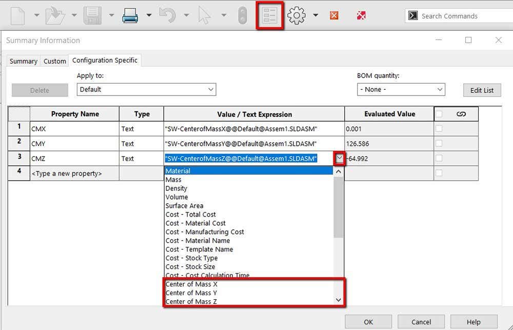
Summary information window where COM coordinate points are mapped to a custom property.
Selecting the cell under the Property Name will allow you to create a new Custom Property. The exact names do not matter, but I use CMX, CMY and CMZ. The cell under Value/ Text Expression is where you link the Property Name to the center of mass location. If you hit the arrow at the right end of the cell a drop-down list of SOLIDWORKS properties is available, as seen above. As you can see in the Evaluated Value cell, the Custom Properties now equal the appropriate coordinate values of the assembly’s COM. Make sure to note the vectors as dimensions cannot be a negative number.
Creating a Sketch Point
In a 3D sketch, you want to sketch a chain of three lines from the origin in orthogonal directions that match the aforementioned vectors. If you have a negative value, make sure you sketch the line in the negative direction. In this example, there will be no line in the x-direction and the Z line should be in the negative direction, as seen in the image below. The design intent of this example is to have symmetry across the YZ plane so the Center of mass will always have x=0 so no line is needed. If I did not want to guarantee that symmetric condition then creating a line in the x direction would be recommended in case a drastic change is made. Make sure that each line has a relationship along one of the standard axes.
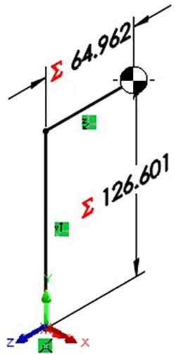
3D sketch with an endpoint on the center of mass.
The next step is to link the length of the line to the corresponding Custom Property by using equations. Inside of the Modify box of the dimension, typing in the equals sign will activate equations and will generate a drop-down list of options to link the dimension to. This list will include the created Custom Properties as seen in the figure below. The Modify box shown below is for the line in the Z direction. You can see that dimension is linked to the absolute value of the Custom Property by using the abs() function. Since you cannot have a negative number as a dimension, the absolute value function has to be used and the direction is determined by the initial direction of the sketch entity. This can cause some issues if there are significant changes to the assembly and the center of mass passes the origin.
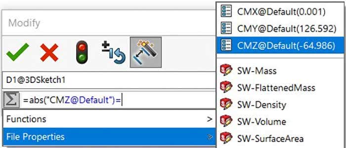
Dimension modify box where the value is linked to a custom property.
Once the three dimensions are linked to the three custom properties you will have to select an endpoint that is relative to the center of mass location.
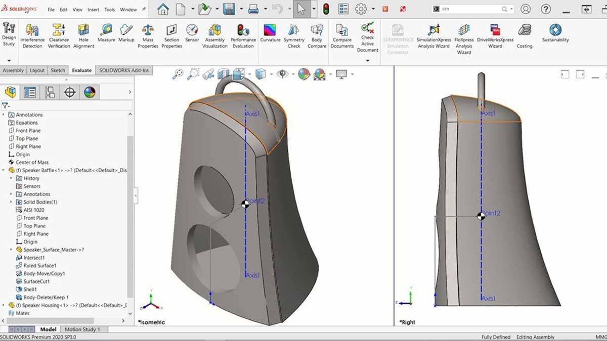
Use Case
For an example, I want to hang this speaker in a level orientation and not have it swing. To achieve that, I created a mounting point directly above the assembly’s COM inside of the part file. Since the COM was parametric, it would relocate as I created new geometry. The video below demonstrates the assemblies COM and the relative mount relocating after changing the material in the assembly environment. When you are in the assembly environment make sure your parts have the appropriate material applied. If no material is applied, the density of the part will default to the density of water (1g/cm^3) and that could really throw off your center of mass.
Gif illustrating the link between the assemblies center of mass and the location of the hanging bracket.
For more information on SOLIDWORKS, check out our YouTube channel or contact us at Hawk Ridge Systems today. Thanks for reading!


