Anyone who has ever had a pop-up camper knows how tedious it can be to raise and lower the roof.
For those that haven’t had the pleasure of completing this arduous task, there is a receptacle on the side of the camper that you plug the hand crank into and get to cranking like a kid spinning an ice cream maker – except instead of a frozen treat, the result is more standing room for your weekend.
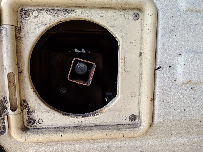
Figuring that someone would’ve already thought of a way to complete this with a hand drill, I scoured the internet for a drill bit that would do the trick, but found nothing. Upon inspection of the hand-tool geometry and how it fit in the receiver, I discovered that the receptacle that the hand crank plugs into is a non-standard 7/8″ square – easy enough, right?
The basic part of the CAD model would be super simple.
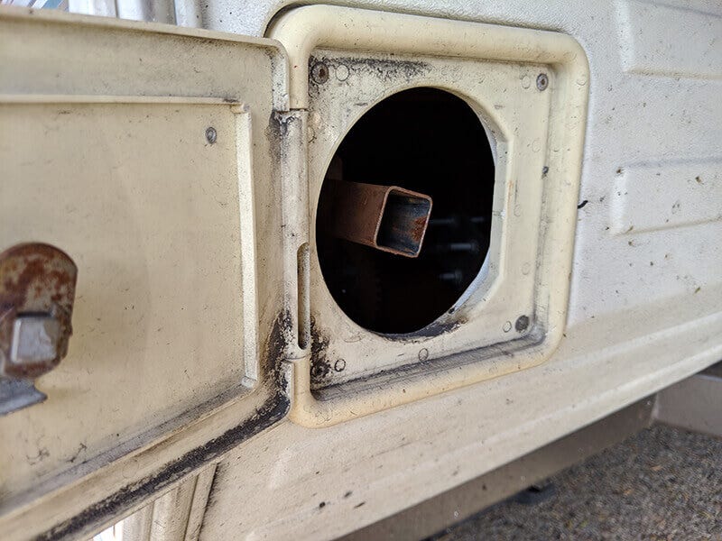
Trailer receiver for raising and lowering the pop-up roof.
I decided to design my own custom bit.
The Design Process
From here, I needed to decide how to connect that to the drill bit. Most would think creating the CAD geometry as an integrated stem to the bit, but from an engineering perspective and Metal X best practices, I decided to take a different approach. I designed it just like a socket wrench bit, so I could then simply buy a 3/8″ socket extension to connect to the drill.
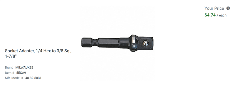
Example ⅜ socket adapter from McMaster-Carr.
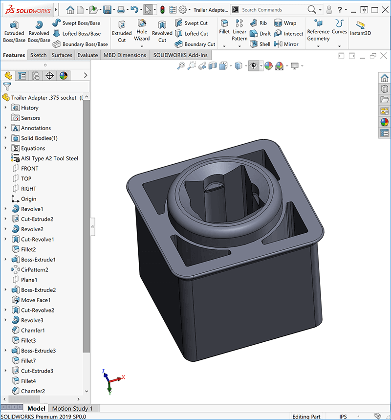
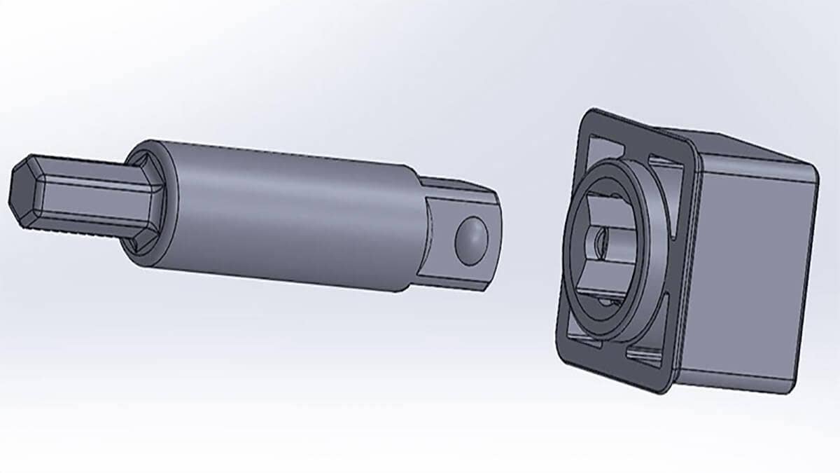
Custom bit designed in SOLIDWORKS.
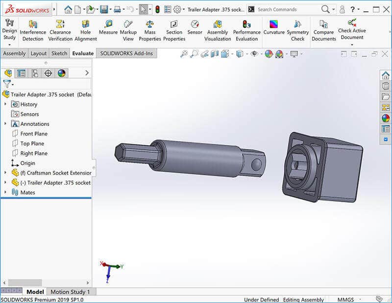
Custom bit and adapter modeled in SOLIDWORKS.
Here is the excerpt from Markforged that refers to this technique:
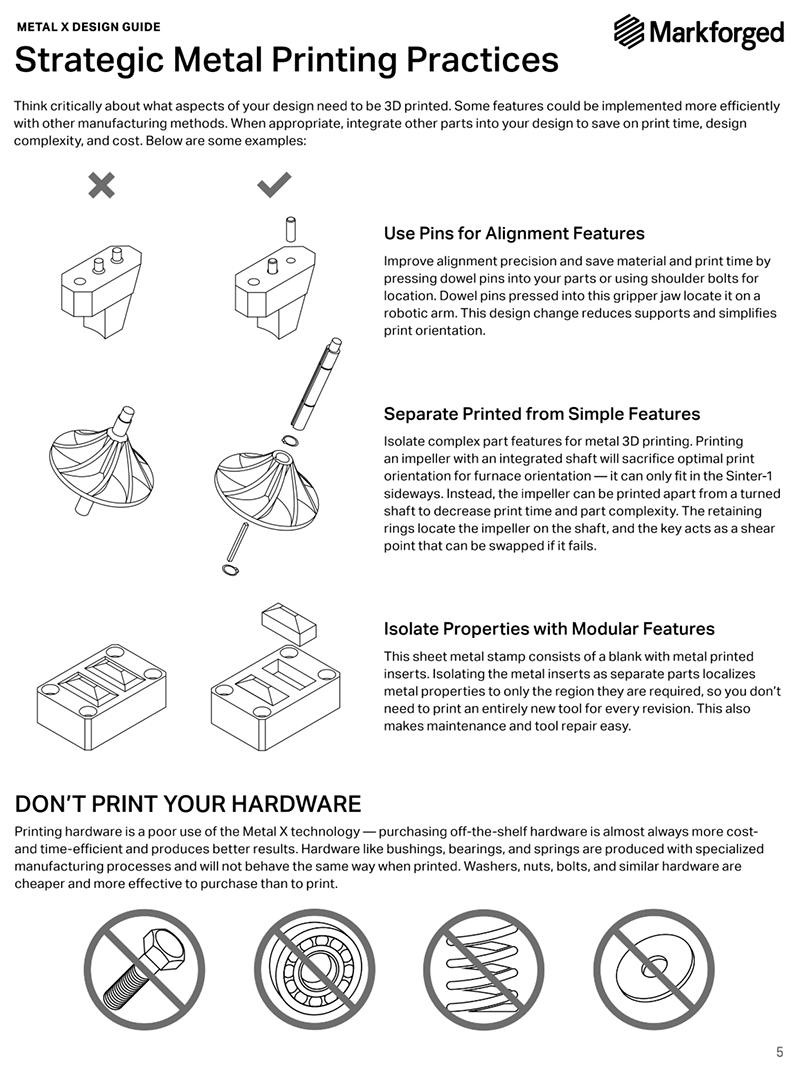
From Markforged Metal X design guide.
Again to speed things up, I went to a popular open source CAD website that has shared content and found a perfect socket extension with a matching socket wrench head. SOLIDWORKS is capable of opening pretty much any file type, even generic meshes, and allows me to use the geometry. I was able to take the female receiving portion of the 3/8″ bit and incorporate it into my custom bit design.
I then did a quick print on the Mark X7 in plastic to do a fit check, for both the bit geometry and the trailer receiver. Doing this in plastic meant I had something in my hands in a couple hours at about $1 to confirm the CAD model I borrowed was designed accurately (I didn’t need any calipers or to waste time reading up on 3/8″ socket head geometry specifications). It fit like a charm!
Since I had it in hand and the part fit nicely, I figured “why not see if the plastic piece works?” It didn’t, the bit stripped out the inside pretty quickly with the large torque needed to lift the trailer.
Detailing Remaining Features
Now that I had the critical dimensions, I went to detailing the remaining features:
- I put a chamfered stop on the rim of the bit so it wouldn’t slide too far into the receiver.
- I added pockets to remove material usage (both for cost and weight savings), this also created more uniform thickness geometry and added more surface area for debinding).
- I modified the detent tab for holding the 3/8″ bit so that the overhang throughout the model was not more than 45 degrees – meaning no support material was needed.
- I added a chamfered center hole for more material reduction.
I broke all other edges with a chamfer or a fillet – it depends on the geometry’s orientation compared to the print orientation. That’s because an edge fillet in the x or y-axis directions would result in a curvature creating more than 45-degree overhang, any edges that are within 45 degrees of the z-axis can be filleted without a need for supports.
Here is an image of that being applied, notice the bottom facing (referring to print orientation, shown here with an arrow in the z-direction) doesn’t have a fillet (green faces) on the chamfered edge (pink face), but the other side on the vertical face do.
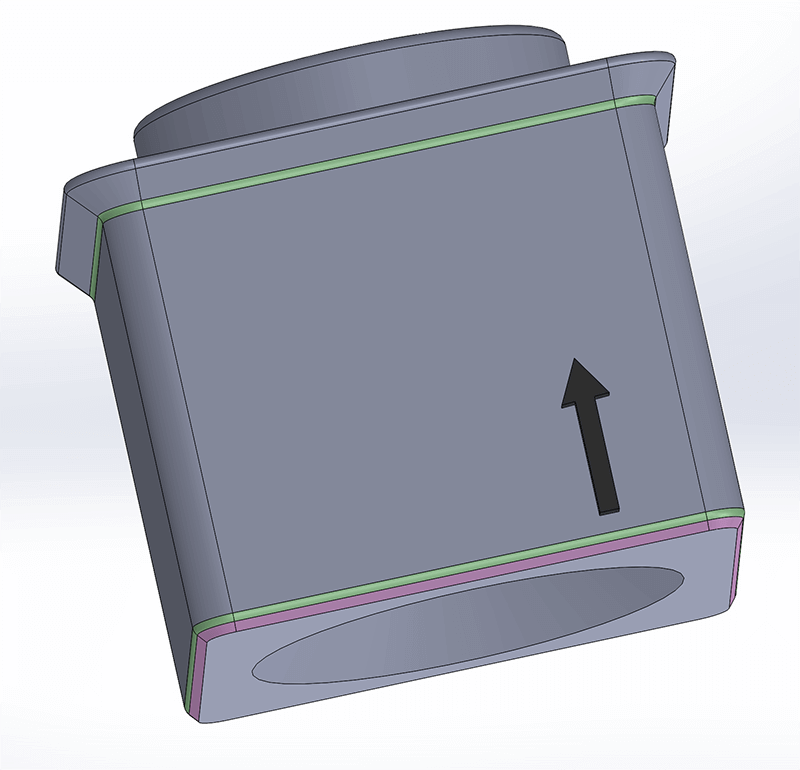
Avoiding overhang.
I reduced material as much as possible since the stainless-steel material had tons of strength. Aside from that, if I found out it was too weak, I could edit the parametric model and quickly have a new, beefier model printed fast – the power of 3D printing! My only real limitation was the minimum wall thickness recommended in the design guide. Unlike designing for plastic injection molded parts, I was worried about a constant wall thickness though, since that’s not an issue with 3D printing.
I printed the final model and the part works perfectly!
The design incorporates many of the strengths of the Markforged Metal X:
- One-off value
- Quick turnaround
- Strong, fully-sintered metal
The project also utilized some of best design practices specific to Metal X atomic diffusion additive manufacturing (ADAM) technology, typically known as design for additive manufacturing (DfAM).
The full cost would be about $18 for materials and the sintering run consumes about $80 worth of argon and electricity, but assuming a batch of 40 would be sintered, it would be $2 per part. It took about 65 hours from print to final sintered part with limited operator time of starting print, and transferring from print, to wash, to sinter, but it’s important to note that the washing and sintering process are hands-off processes, so it would be done in batches and there is economy scale factors in play.
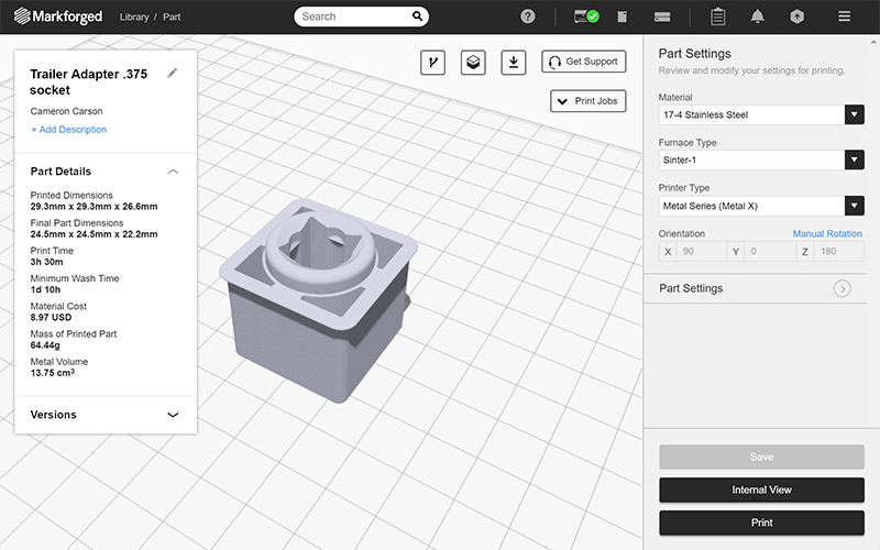
Adapter part shown in Markforged Eiger software.
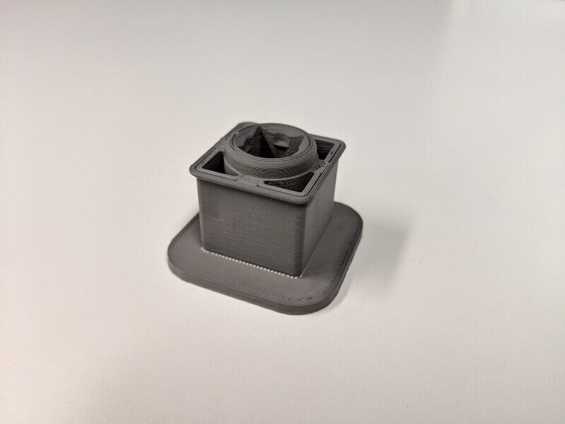
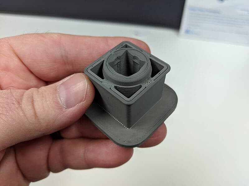
Adapter part in right off the printer in the “green state,” prior to sintering.
If 3D printing technology could be used in a simple, real-life situation like a crank bit for a pop-up camper, imagine the possibilities it could unleash for you and your organization. If you’d like to learn more about additive manufacturing, CONTACT US and we will point you in the right direction. Thanks for reading!


