
In a previous blog, we used the
Compare Geometry
tool to analyze two versions of the same part to quickly identify any
geometric similarities and differences. This time around, we’re going to take
a look at the Compare Features tool. The Compare Features tool works very
similarly to the Compare Geometry tool, but instead identifies the differences
in actual solid features, including appearance properties.
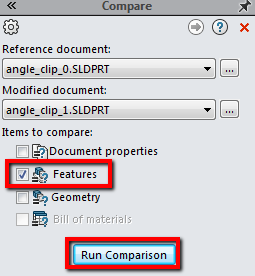
To use the tool, click on Tools > Compare > Features.
This will turn on the Utilities Add-In if it was not already turned on, and
will also expand the Task Pane with the Compare tool active. From here we can
select the two files we want to compare features. If you already have the
files opened in SOLIDWORKS, select them from the drop down menus for Reference
and Modified Documents. If not, you can browse for each of the files. Under
Items to Compare, select Features and click
Run Comparison.
Compare Features references the FeatureManager Design Trees from the two parts
and compares the list of features by name and type. These features are
classified as either Unique Features or Modified Features. Unique features
have their own name and type and appear exclusively in one part or the other,
whereas Modified features have the same name and type and are in both parts.
When Modified Features are found, the tool pairs them together and compares
their individual parameters. This helps distinguish what features may have
been added/removed, or had parameter values changed from one version of a part
to the other.
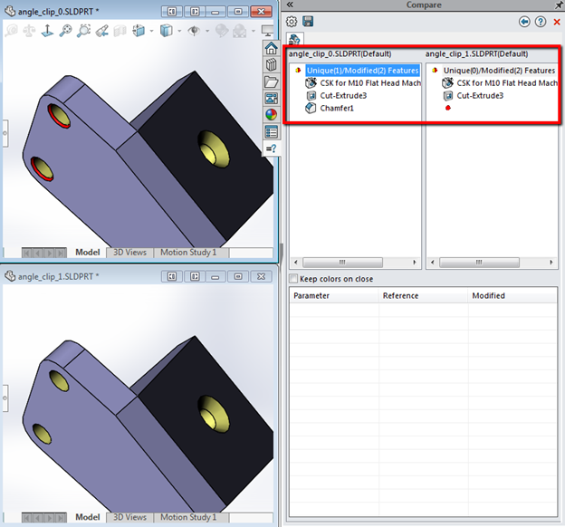
The results will be listed in the Task Pane, showing each of the
Unique Features and Modified Features for
each of the parts (if any). If you click the top level feature (Unique (1)/Modified(2) Features), the Unique and Modified Features are color coded in the graphics area to
show where the differences are between the two parts. It also shows a red dot
in place of a feature icon if a Unique Feature doesn’t exist in that version
of the part.
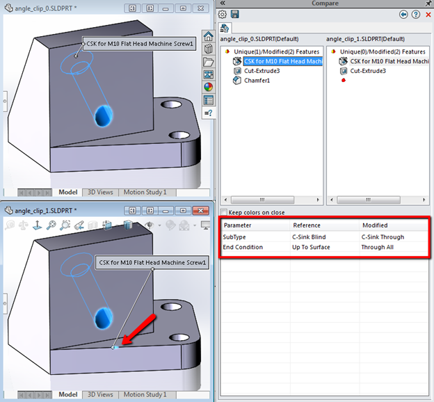
Furthermore, if you click on a Modified Feature from the list, the feature is
highlighted on both parts in the graphics area and the parameters for that
feature will be listed below. In this example, both parts have the “CSK for
M10 Flat Head Machine Screw1” feature, but one has an Up To Surface end
condition and the other has a Through All end condition. The tool will detect
any differences in sketch geometry as well, which is why Cut-Extrude3 is on
the list as a Modified Feature.
The results for the Compare Features can be saved in a by clicking on the
Save Report icon at the top of the Compare Task Pane. We can
see how the Compare Features tool differs from the Compare Geometry tool. Both
work great to quickly compare two versions of the same part, but each has
their specific uses. Be sure to check out our
YouTube channel for
more helpful tips!


