If you’re a pistonhead like me (that’s a gearhead to you North Americans),
chances are you have or will be trawling the for-sale ads in the forums,
eBay, or Craigslist at some point in your life. I was on the hunt for a “new”
engine for my project car and found what I thought was a great deal, so I
jumped on the phone and arranged a meeting for that weekend.
I showed up to a garage that can only be described as a crumbling old shack,
parts strewn all over the place and with about as much light as a hobbit’s
cave. Inspection light in hand, I looked over the engine. The crank turned
over so at least it wasn’t seized, but the block was a little rusty. I found
out it’s originally from the East Coast of the Great White North (aka Canada,
eh?!) where the roads are made from salt. That explains the so-called
“surface” rust. The clues were all there; inlet manifold half dismantled with
a leaky roof dripping next to the engine. It didn’t take Lt. Columbo to spot
the potential problems but since I already planned to do a full rebuild, it
seemed worth a risk. Armed with Gas Monkey Garage powers of negotiation, I got
the price down to something we’ll call reasonable and shook hands (the other
half might read this so I’ll leave the actual price out).
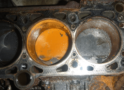
So I get back to my shop and start stripping it down. The head looks like with
a little work it’ll come up great, but sure enough the bores looked like
they’d visited a spray tan salon, being covered in a thick orange paste. After
a little clean up, the liners were clearly pitted. It needed machining.
Fortunately a local machine shop could help me out and they did a fine job.
I was curious to find what’s involved with CNC boring an engine. Mine was only
a “four banger” but I thought it would be more interesting to see how we’d go
about programming a V8 in
CAMWorks.
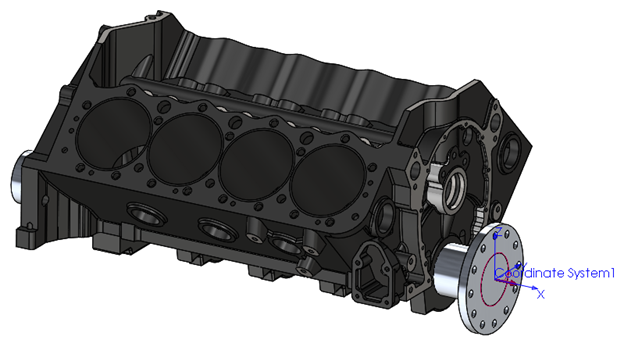
I started by creating an assembly which comprises of the block itself,
including the main bearing caps which clamped onto a dummy crankshaft. This
whole assembly mounts to the rotary table and steady in our machine. By using
the crankshaft as our rotary axis, it was easy to position the top of the
block at the correct angle to bore the cylinders. I added a
coordinate system in
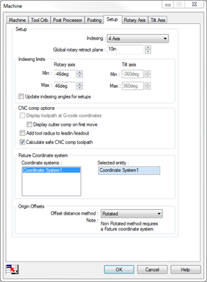
SOLIDWORKS to use as a Fixture Coordinate System and then defined that in the
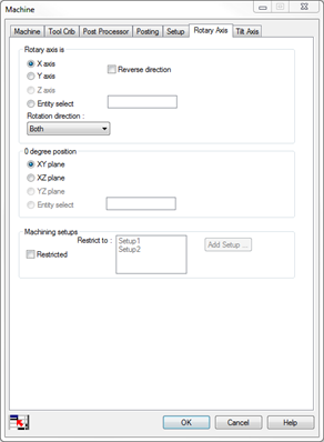
Machine>Setup tab. I set up my indexing parameters so that
I automatically get the positional move to machine the other bank. In this
case we’re using 4 Axis with the
rotary about the X direction and we don’t
want to crash the block into the table, so I set up some
indexing limits. This block has a 90-deg V-Angle so I used
limits of -46° and +46°, which should help reduce the number of positioning
angle solutions later.
At this point, I needed to check tolerances by probing the bores in the X
and Y directions to verify that they are what the manufacturer states they
are. If they’re off then I’d need to make a decision on which to follow;
I don’t want the bores to be misaligned with the crankshaft. Once confirmed,
I added the setups and appropriate
circular pocket features to each setup. My database didn’t
have a bore strategy for such a diameter so I inserted the operations myself.
I tweaked a few parameters to control the finish including setting our
tool size to the appropriate bore diameter.
I also added a chamfer operation to clean the lip at the deck
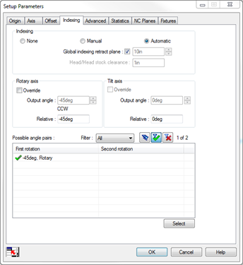
to make piston insertion a little easier. Once I had that set, I
double-clicked on each setup and set the origin and axis tabs
to Fixture Coordinate System. I also set my
G54 work offset and double-checked the
indexing angles are correct. In this case -45° and +45° with
a 90deg relative movement works, but it’s worth checking! I don’t want the
table to do a 270° move between setups and end up with the block crashing into
the table. In the fixtures tab I added the
dummy crankshaft, but since I’m nowhere near the crankshaft
there’s no need to avoid it.
I wanted to make sure that I minimized rapid moves. After all, time is money!
To sort the order of the features, I can use the
Optimize tab in the operation to set it to
Shortest Path and Last Closest. To minimize
tool changes, I right- clicked on the Machine and used Sort Operations. I wanted the boring to be done first on all cylinders and then chamfered
second. I used the By and Across Setups and put the
Bore before the Contour mill.
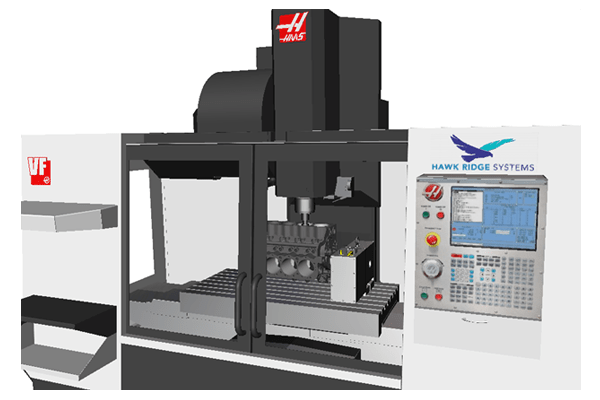
One final check before running was to test it in the virtual
machine simulator to make sure everything was set
correctly and there weren’t any gouges or collisions. No gouges, no collisions
and no long rapid moves.

If I was doing this on a regular basis, then I’d just save my circular pocket
feature back to the database using Save Operation Plan. That
way I’ll only have to change the bore diameter and it’ll automatically create
the chamfering operations for me the next time.
So there you have it, how to CNC bore an engine block in CAMWorks. And if
you’re looking for finished pictures of a clean and shiny rebuilt engine,
well… you’ll just have to wait. It’s work in progress… just like the deck
that you started 10 years ago!