With media coverage of the World Cup dominating news and sports sites,
you may have missed some other major sporting events, most notably the
Le Mans 24hr and the Nürburgring 24hr. Whether it’s nostalgia and the opportunity to see some of motor racing’s elite at the French race, or the attraction of camping in a forest listening to cheesy Euro pop while slurping copious amounts of high-quality beer at the German event, both provide an incredible experience
for a motorsport fan.
This year’s races were no different, giving fans an plenty of action as
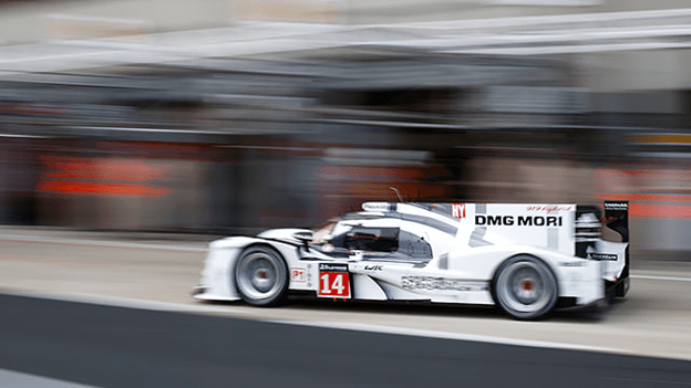
Audi dominated the show in both events. But it’s not Audi that caught my
eye this year. It was Porsche, returning to racing at the Le Mans 24hr
with its 919 Hybrid. Late last year, Porsche also set a blistering lap of
the Nürburgring with its 918 Hybrid.

Porsche’s Energy Recovery System Attached to the Turbo
I’m usually a little apprehensive when it comes to hybrid and electric vehicles but I was curious to find out more about the powertrain being used. To my surprise, I found out that the 919 Hybrid was running a comparatively miniscule 2 liter turbo V4 (half a V8 essentially) gasoline engine rather than the diesel engines favored by the successful Audi and Peugeot factory teams of previous years. The hybrid aspect came from all-electric driven front axles with a Kinetic Energy Recovery System (KERS) and a secondary system attached to the turbo. While not on boost, the system recycles the kinetic energy of the exhaust gases flowing through the turbo and uses it to recharge the batteries. You would also presume that it works in reverse to spool up the turbo a bit like the anti-lag used in World Rally Cars. Coincidentally, Audi also featured a similar system on their race-winning LMP cars this year.
I couldn’t resist the opportunity to create a CAMWorks article on this fascinating technology. Given that the Porsche 919 Hybrid was sponsored by DMG Mori, it just made sense to have it related to machining a turbo impeller. So what’s involved?
Given the blade geometry we need to use 5 axis machining; we’ll focus on
that. We’ll need to rough out between the blades and then do some finishing
work to clean up the surfaces. To make life easier, we’ll just program one
portion and then pattern our toolpath around later.
First up, we add our Mill Part Setup. In this case I’m going to use our Front plane since the Z axis is already pointed in the correct direction. I’ll create the roughing toolpath first. For that, we need to define the region in between the blades. We’ll use the opposing faces of the two blades to define that volume and I’ll use my 5 axis strategy.

Drive Surfaces for Roughing Operation
I’ll use Generate Operation Plan to get my 5 axis operation and then I’ll edit some settings. A great place to start is to check our tool length, so we’ll adjust the Protrusion on the Mill Holder tab to 2.25” in this case. Next up is Pattern type and we’ll use a Flowline between Surfaces so that we can set the upper and lower limits of our volume to machine. We’ll use the faces at the tip of the blades for the Upper surface and the radius at the root of the blade for the Lower surface.

Upper Drive Surfaces

Lower Drive Surfaces
We’ll set the Entry/Retract up to be Cylinder about Z to prevent it from retracting vertically through a blade and set the radius to 6” in this case. We’ll set the Leadin and Leadout to Tangent Arcs at 50% of the tool diameter.
Since our drive feature is the walls of the blade, we want to use the side of the tool to swarf cut it rather than using the tip. We could use the dedicated Impeller machining options, but for sake of completeness let’s use the Tilted Relative to Cutting Direction and set the Side Tilt to 90°.

To create the Roughing passes, we’ll use the Area Roughing option from the Roughing tab. Check the box and use the button next to the check box to define the roughing parameters. We want to ensure that the toolpath we generate is gouge-free so we’ll need to use the After Gouge Checking option. Note that the Stepover in the Pattern tab controls the depth of cut in this case whereas the Max Stepover here controls the stepover to the side. We’ll keep the Trim Cuts enabled here to get rid of any unwanted oscillations that can often occur at the edges of the surface. To ensure we clean out all of the material, I’ll extend the toolpath using the Extend/Trim option on the Finish tab.

Now that we have the area roughing enabled we also need to control the links
between the passes. We don’t want to bury the cutter into the material during a link move so we’ll set our Links between Passes to Clearance. Since we’re here we may as well set our Links Between Cuts to Blend Spline to avoid any sharp corners during link moves.

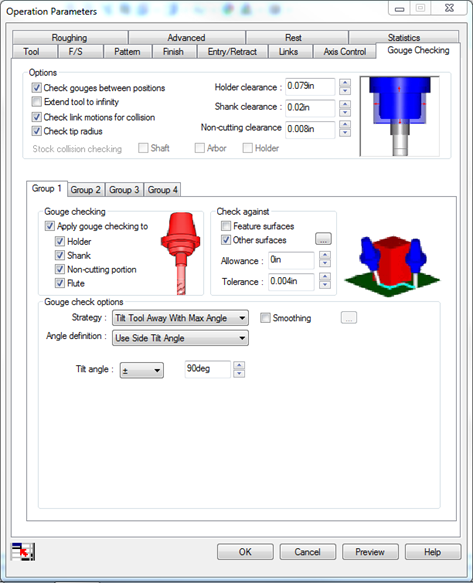
To ensure we get clean gouge-free toolpath and avoid any unwanted collisions with our tool and holder we should use the gouge check tools. We’ll set our clearances for our tool and holder, and ensure we’re gouge checking the entire toolpath by using the Check Link Motions for Collisions. We’ll gouge everything for the tool and holder and use the Tilt Tool Away with Max Angle and Side Tilt option to force the tool to lean away from any potential gouge. We’ll use the Other Surfaces to control what it gouge checks against. Create a feature that has all the faces in close proximity to the blade as shown.

Gouge Check Surfaces
For the finishing pass we’ll create a feature for just one blade using the leading and trailing surfaces as well as the radius between the two faces. We’ll use the same tool, the same Flowline Between Surfaces pattern type, same settings for Entry/Retract, Links, Axis Control and Gouge Checking.

Drive Surfaces for Finishing Pass
Once we have the roughing and the finishing passes created we’ll pattern them around using a circular pattern. Right-click on the Multi Surface Features used to create the operations and choose the Pattern>Create Pattern Option. Using a Circular Pattern option and the cylindrical face of the turbine shaft hole as the reference axis, we’ll create a pattern for the 12 blades.
One final thing is to run the G-code through our Virtual Machine. As the Porsche team was sponsored by DMG Mori, what better than to see it run in a DMU 60T 5 axis Head-Table machine? Not only can I verify that the toolpath I generated is gouge free, I can also verify that the post processor is working correctly without risking crashing the head into the table.
So that’s how to program a turbo impeller in CAMWorks. Sadly, the Porsche team didn’t finish the race and Audi took another two podium spots – but the real winner from this is the general public. Consider this beta testing of technology you’ll see in your road car in the next few years. Exciting stuff!