Are you struggling with getting a SOLIDWORKS assembly started, or continuing an assembly that’s already been started? If so, this is the article for you. Please keep reading for steps and tips on creating an assembly from scratch, what all of the icons mean, and adding parts and subassemblies to assemblies.
I need to create a hinge assembly and add it to a door. An assembly is a collection of parts and/or assemblies in one file. I already have the parts designed, so I’ll use the New command to create an assembly. Here, I can choose the generic assembly template, or click on Advanced to specify a custom template.
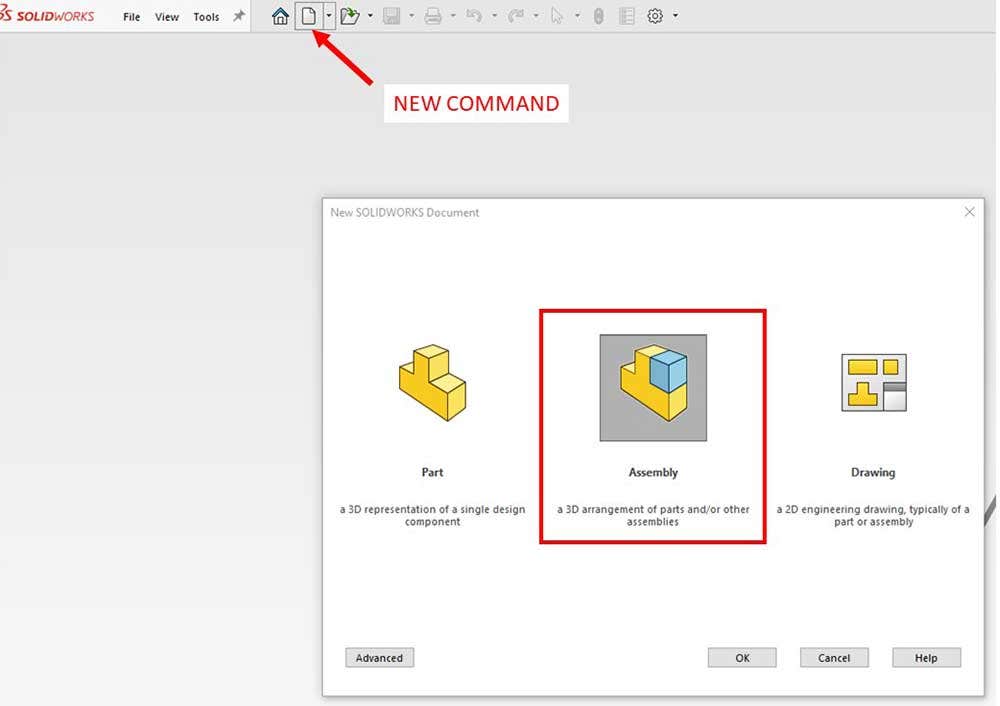
Starting a new assembly.
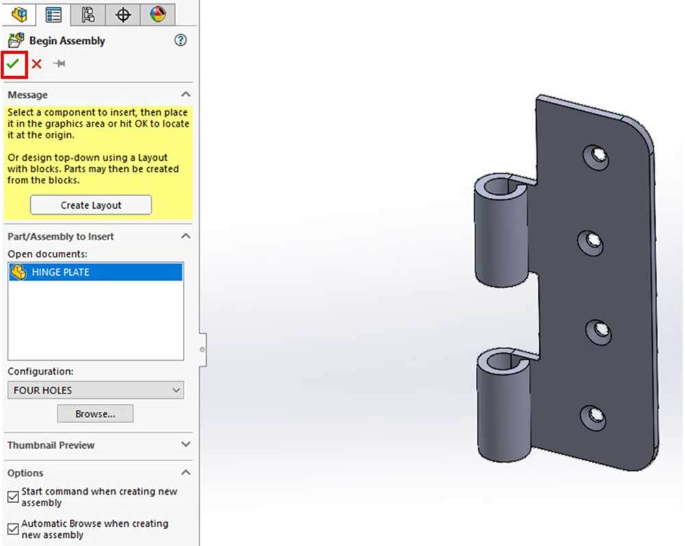
Once I start a new assembly, the Begin Assembly command starts automatically. If I had any files open, they would show up in the Open documents box. I can expand the Thumbnail Preview section to see a preview. There are already options checked on, such as Automatic Browse when creating a new assembly, which will open up the browser. I’ll navigate to the file I want and open it. Notice I can select the configuration and display state when I’m adding the part, but I can also change that later on.
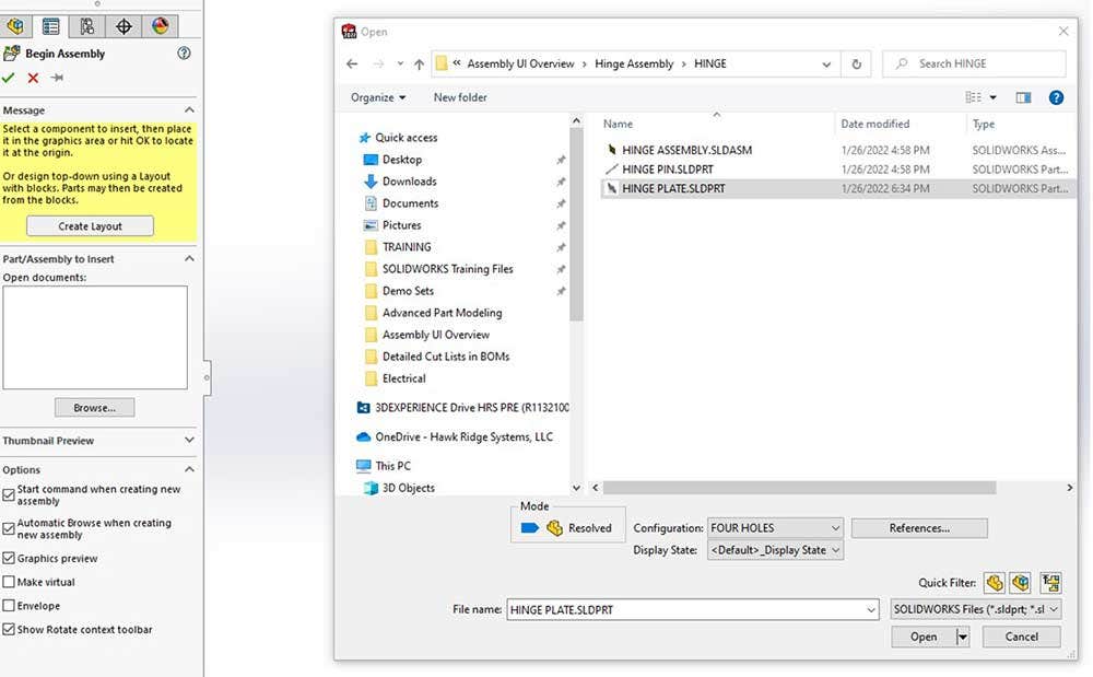
Begin Assembly Command.
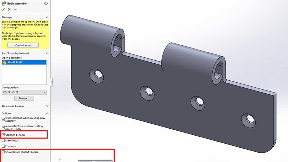
Once I’ve selected it, having the Graphics preview option checked will allow me to see it in the Graphics area. The last option allows you to rotate the part before you place it, which I’ll use to make the hinge plate vertical. By default, the part’s orientation is what it was designed in. You can change the angle to whatever you like, and click the button on the axis you want to rotate about respectively to the global coordinate system in the bottom left of the Graphics Area.
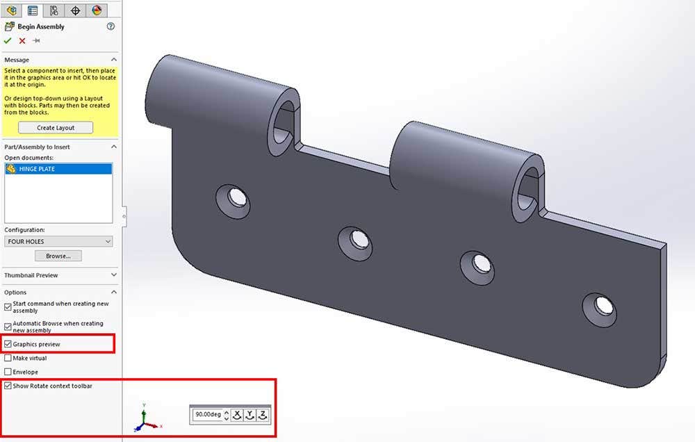
Placing the part in the assembly.
Notice that you can move the part around the Graphics Area freely, even after rotating it. If you left-click somewhere in the graphics area, it will place the part in the assembly at that spot. However, I recommend when you put in the first part that you hit the green check in the Property Manager. This will place the part at the Origin of the assembly and fix it in space.
Hit Okay to place the first part at the origin.
Let’s take a look at the User Interface. When working in an assembly, the Assembly tab is on in the Command Manager and this is where you will see most of the commands useful while building and modifying an assembly. The icon in the Feature Manager tree next to the name indicates that this is an assembly. Moving down the Feature Manager tree, there are the same folders we would see in a part, along with the standard Front, Right, Top planes, and Origin. These are the assembly reference planes. At the very bottom of the tree, there is a Mates folder that is currently empty. More on this later.
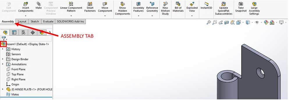
Assembly UI.
If I expand the part, I can see that it has its own reference planes and origin. When I clicked Okay to place it, the part’s planes were aligned with the assembly’s planes. There’s an F next to the part name, which means it’s fixed in space and cannot move. In other words, all of its degrees of freedom have been locked. I can also see which is the current configuration and display state.
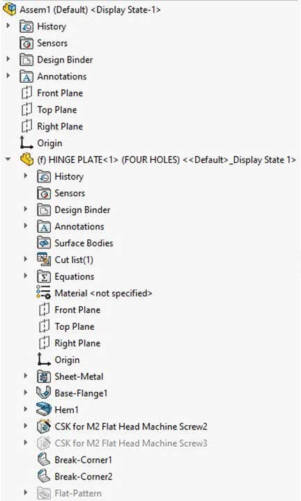
Expanded Feature Manager Tree.
I recommend at least one part or subassembly be fixed so that it can anchor the other components in the assembly. I want to add in another part, so I’ll use the Insert Components command.
Because there’s no other part open in SOLIDWORKS, an Explorer window opens up. Otherwise, using the Browse button will accomplish the same thing. Now I’ll pick the HINGE PIN to add. I could use the rotate toolbar but this time I’ll just place the pin close to the plate. I don’t want to hit the green check because I want to be able to move the pin.
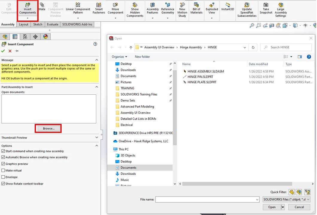
Insert Components command.
Looking in the Feature Manager tree, I can see that the pin can move, indicated by the minus sign next to the name. In other words, there aren’t enough degrees of freedom locked to keep the pin from moving. To translate it in space, left-click a face and drag. To rotate it, right-click a face and drag. Just a reminder, I can’t do that with the plate because it’s fixed (you’ll get a message if you try to move it.) However, I can right-click on it and select Float to change that.
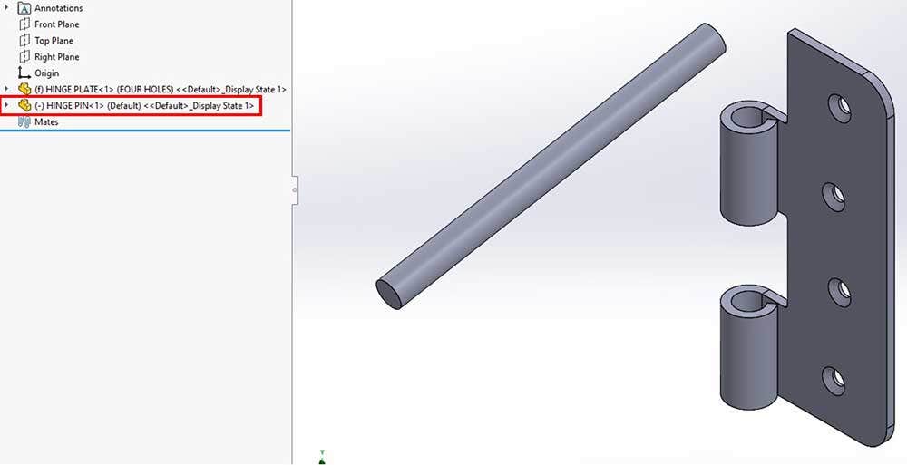
Unconstrained second part.
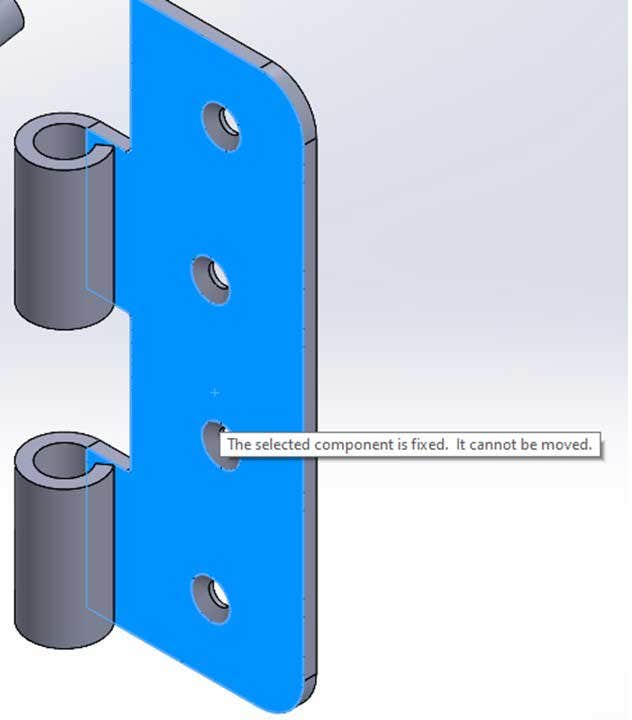
Fixed component message.
Before I mate a part, I like to move it close to its final position. This makes it easier for me to predict how SOLIDWORKS will apply the mates. Speaking of mates, let’s add some. I’ll hit the mate command up here.
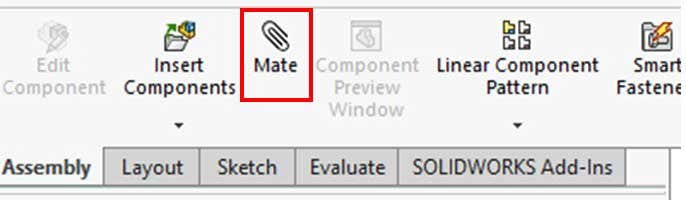
Mate Command.
As you can see, there are many different mates and categories of mates, but I just need the standard ones. You can preselect the mate you want, but I like to select the entities that I want to mate and SOLIDWORKS will take a guess at the mate. Usually, this is correct, but can be changed.
For the first mate, I’ll select the outside of the pin and the outside cylindrical face on the plate. When you select the first face of the first part, the whole part becomes transparent to help with mating the corresponding part. The pin moves to the correct position and a mate toolbar pops up with the concentric mate selected. I don’t have to choose the inside face on the plate because the software is mating the center axes. I can change the type of mate or flip the alignment of the mate as well as undo the mate. This can either be done in the Property Manager or on the pop-up toolbar in the Graphics Area. Keep in mind that the mate hasn’t been added until you click the green check.
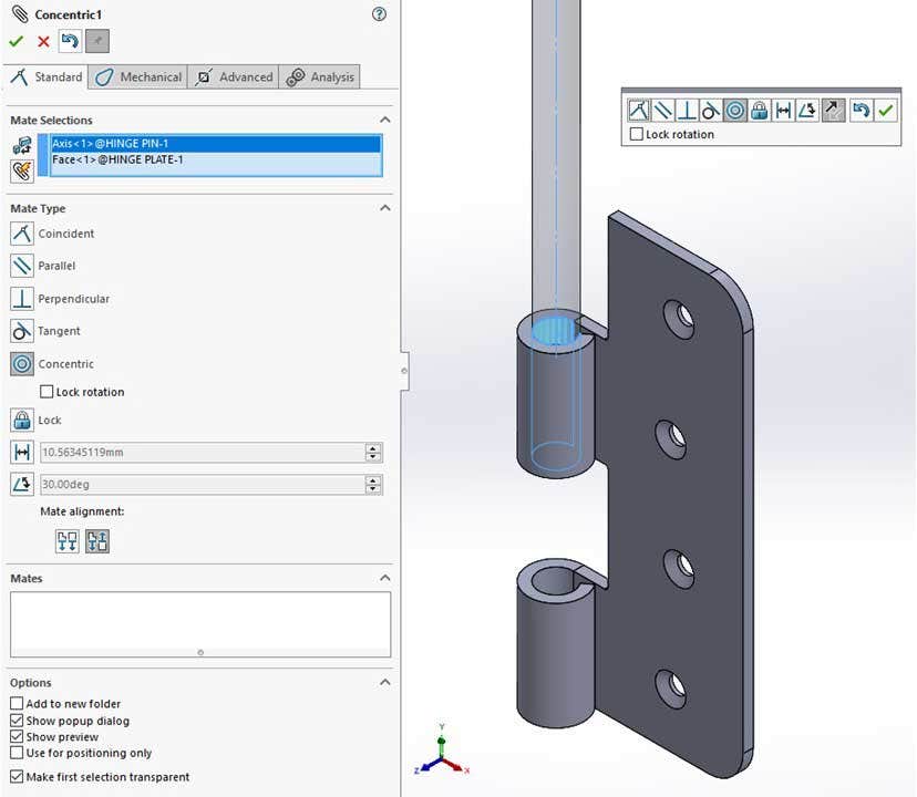
Creating the first mate.
I’ll rotate around the entire assembly and move the pin so that I can select both flat faces and make those coincident. After selecting okay, the mates have been added to the Mates box. Once I’m done with the Mate command, I select okay at the top of the Property Manager to exit the command.
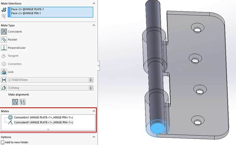
Mates added to the assembly.
Now that there are mates in the assembly, I can expand the Mate folder to see them. This is helpful for seeing all of the mates in the assembly, but when you’re looking for a mate that pertains to a part, you can expand the part to view this folder. Clicking on a mate highlights the entities involved in it.
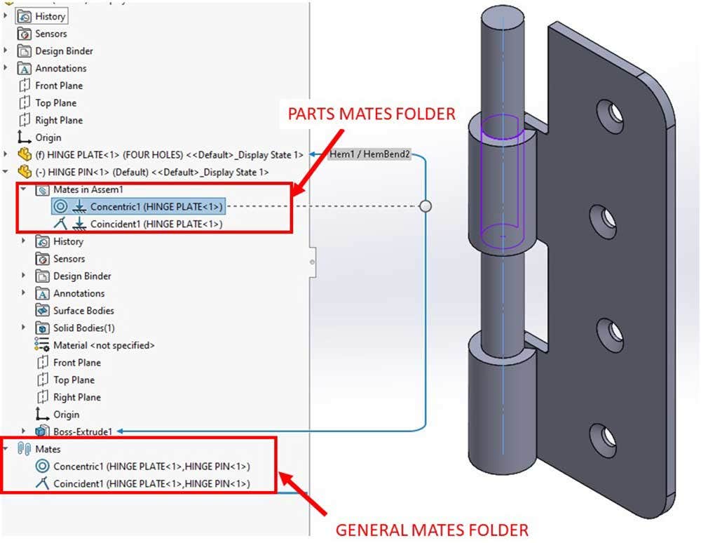
Mates folders.
Even though I’ve added mates, the minus is still next to the pin. That’s because I can still rotate the pin about its axis. I don’t need that rotation, so I’ll right-click on the concentric mate and select Lock rotation. The minus goes away and all of the degrees of freedom are locked. If you’re working with a non-cylindrical part, you can add more mates as needed. However, if you add too many you will get a warning that the part is over defined.
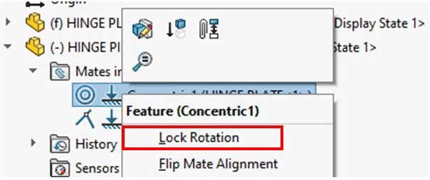
Lock Rotation option.
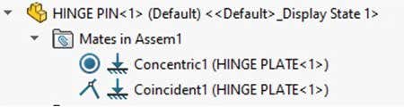
Fully locked part.
Lastly, I need to add in a second hinge plate. I could use Insert components again, but it might be easier to copy the first one. I can do this by selecting it in the Feature Manager tree, holding CTRL, and dragging it into the Graphics Area. Before I mate it, I have another configuration that I want to use. By right-clicking on the part, I can select the correct configuration at the top of the menu by selecting it in the pulldown and hitting the green check.
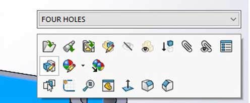
Changing the configuration used in the assembly.
Now, I’ll add in enough mates to position it, but not enough to fully lock it because I don’t want to keep the hinge from rotating. Also, note that the second instance of the same part has a “2” after the name. I’ll save the assembly by hitting Save and giving it a name.
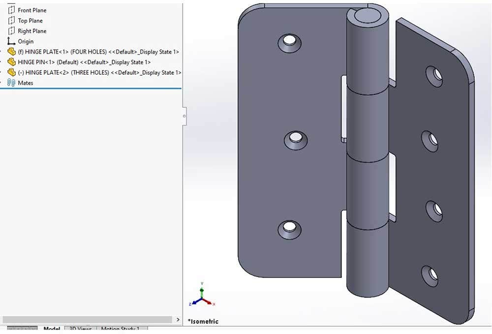
Full assembly.
I want to create a new assembly with the hinge and a door. Instead of selecting the New command, I’ll expand the arrow next to it and select Make Assembly from Part/Assembly to start a new assembly with the hinge assembly being the first part of it.
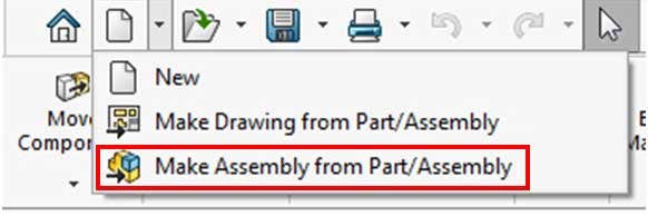
Make Assembly from Part/Assembly command.
I’ll place the hinge using the same steps as above except I’ll place it so that it’s floating. I’ll use the Insert Components command to bring in the door and click the green check to fix this at the origin, then use mates to attach the hinge to it. The last mate is a distance mate, specifying a set distance between the mate entities.
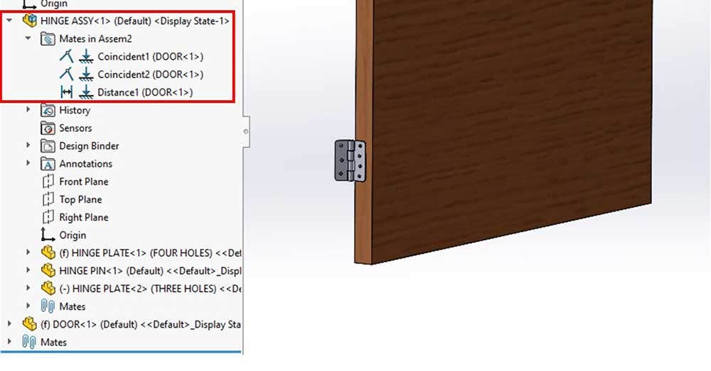
Hinge subassembly fully mated.
The HINGE ASSEMBLY is a subassembly. If you recall, in the hinge assembly the hinge could rotate, right? However, when you place a subassembly in an assembly, the positions of the parts are locked in the last saved position. I can show the rotation of the hinge by right-clicking on it and selecting, Make Subassembly Flexible. Keep in mind that this isn’t the default behavior because it requires more processing. It’s recommended to leave subassemblies rigid in large assemblies as much as possible.
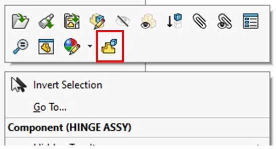
Make Subassembly Flexible command.
Hopefully, this blog gave you some basics on creating and modifying assemblies in SOLIDWORKS. If you have any questions, please contact us at Hawk Ridge Systems. Thanks for reading!


