Additive manufacturing has changed the way that we think about part design and production. The constant innovation of printing technologies and materials is allowing us to continuously print stronger end-use parts. Though additive manufacturing allows for the creation of parts once deemed impossible to produce, design guides should be followed to ensure a part’s ultimate success.
Just like in traditional manufacturing processes – like machining or injection molding – small changes to a part design can drastically increase the strength, durability, and surface finish of a part. Below is a set of steps that are extremely helpful to use when designing a part for additive manufacturing on a Marforged 3D printer.
Determine the Direction of Forces
The first step to guaranteeing a successful print is to understand all the potential forces that a part may encounter. Markforged offers a wide array of plastics and fibers to select in order to meet loading requirements. Due to the nature of Fused Filament Fabrication however, planes that are printed parallel to the print bed are stronger than those in the Z-axis. For critical features that experience a high load, it is important to guarantee that they are printed parallel to the print bed. Oftentimes, when looking at a part it may be difficult to determine what forces it may encounter. Free body diagrams are extremely helpful as they allow a complicated part to be broken down into the individual expected forces.
A free body diagram allows us to analyze any forces or torques that our part may experience in typical use. Using a quick sketch, we can determine which face should be placed parallel to the print bed to maximize the part’s strength characteristics and utilize the ability to print with continuous fiber strands. For simple parts that experience forces in a single direction, selecting the proper print orientation may be simple. Selecting the correct orientation for complex parts that experience forces in perpendicular planes can be a bit more challenging.
There are several options to use for parts that experience forces in multiple directions. One of my favorite options is to section the part into multiple pieces that are each optimized for the expected forces that are applied to them. By sectioning a part, we can take advantage of the continuous fiber placement by optimizing each section of the part for strength and then combining the parts later with bolts, dowel pins, or rods to ensure proper alignment and fit once assembled.
Identify Critical Dimensions
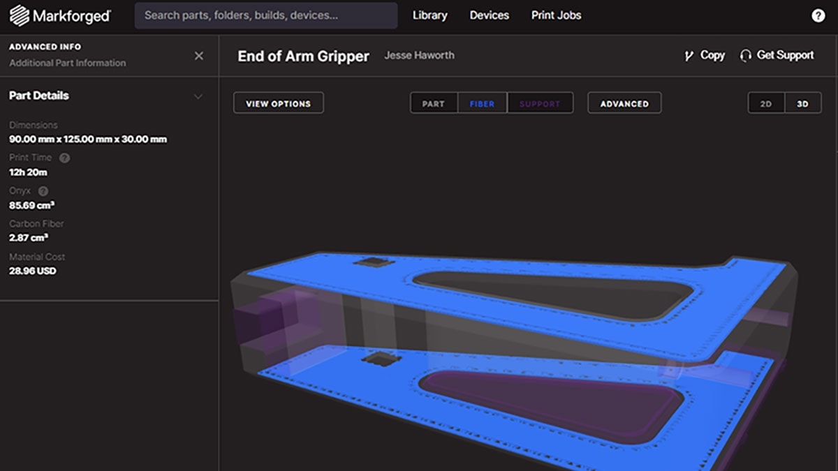
After the part’s best orientation has been established based on force requirements, the next step in designing a part for additive manufacturing is to identify the part’s critical features.
While using a Markforged printer to manufacture a part, dimensional tolerances should be kept in mind. Features that are printed on planes parallel to the build bed will hold a higher tolerance than those printed perpendicular to the bed. With a Markforged printer, the tolerance of features printed parallel with the bed is +/- 250 microns compared with those printed perpendicular which can vary between 50 microns and 250 microns depending on the layer height that is chosen for the print.
Knowing that features parallel to the print bed will print with a higher tolerance, one can make sure to prioritize these faces when printing alignment features or mounting holes. Sometimes it may not be possible to print all the important features on planes parallel with the print bed, this is where additional hardware can come in handy. Using additional components like bushings or heat-set inserts can allow for a feature to be printed perpendicular to the build bed while maintaining the dimensional accuracy required for the particular feature.
Reducing Supports
Once the best build orientation of the part has been established, the next step in designing a part for additive manufacturing is limiting any overhangs or unsupported sections.
Fused Filament Fabrication allows for the creation of complex shapes, however, any overhangs or unsupported sections will need support material if their angle is under 45 degrees. The creation of this support material is necessary for the printing process to ensure that the feature has an adequate surface to print from.
Though supports are necessary for the creation of certain features, there are some downsides to them as well. Support material will increase the printing time of a part and the cost associated with it as well. Once the part has been printed, the removal of any supports will have to be determined as well as any surface imperfections left behind from the removal of support material.
One tool in SOLIDWORKS that is very helpful in determining if supports will be required is Print3D. With Print3D, SOLIDWORKS lets you select on the bottom plane of the part as it is oriented inside of the printer and highlight any faces that will require support. This can be especially useful in the process of designing a part, as it is a quick validation check that can be run almost instantly and gives an idea of how the part as designed will require supports. By analyzing the current state of the part, additional fillets, chamfers or even the addition or subtraction of a feature or face can be applied to reduce the number of supports required, leading to a simpler printed part process.
Chamfering/Filleting Edges
One step of the part design process that will pay off dividends later is ensuring that the part has smooth transitions between faces. With a 3D printed part, stress concentrations can occur at corners. These concentrations can result in a part failing under load that may otherwise meet the printer’s specifications. The simple addition of a fillet on the corner will reduce stresses from forming on the corner, while also saving time in the printing process due to limiting the amount of material required for the part.
Another useful feature to add to the design of a part is a chamfer at the base of the part where it would contact the build bed. After the part has completed printing, releasing the part itself can be challenging at times due to the part geometry being flush to the build bed around the perimeter of the part. By adding a small chamfer to the part, it becomes much easier to leverage a spatula or pry tool under the part without the risk of damaging the part or the bed itself.
Unit Testing
Finally, one of the major advantages of additive manufacturing over other forms of part production is the ability to rapidly iterate a design based upon testing. When committing to produce a part via machining, injecting molding, or casting, a large amount of effort is required to set up the part prior to production. The beauty of additive manufacturing comes in the simplicity of production – simply sending the file to the printer and selecting print. Often with new parts, there may be a small feature or question of fitment that arises during the designing of the part, this is where unit testing can be invaluable.
With unit testing, we can break a part down to the individual features and test print just those features to determine if they will work and or what tolerance and sizing are ideal for our particular application. Unit testing allows you to print a small section of a larger part in a short amount of time to help ensure that one committed to the print and the part itself will be successful.
Traditionally unit testing can be expensive, but with additive manufacturing, a quick test can be performed in relatively little time. Unit tests can be completed many times in as little as 30 minutes – about the time that one would take for a lunch break! By utilizing unit testing through the preliminary design process, the design can be tested and any failures can be found with relatively little impact on deadlines or costs. The concept of failing forward is made possible by utilizing a 3D printer in a design workflow.
Additive manufacturing allows for the creation of complex parts on demand. Utilizing these simple steps through the design process of your part will not only help ensure success but will also help to accelerate the design process as well.
If you’re curious about how Markforged 3D printing technology could work for your organization, contact us at Hawk Ridge Systems. One of our additive manufacturing experts will be happy to help answer your questions. Thanks for reading!