Have you ever seen a colorful 3D printed part showing a stress analysis and wondered how they do it?
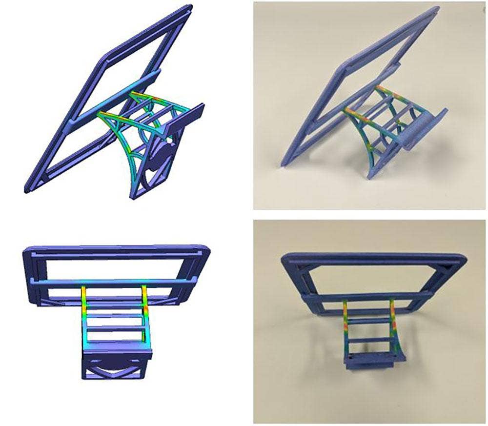
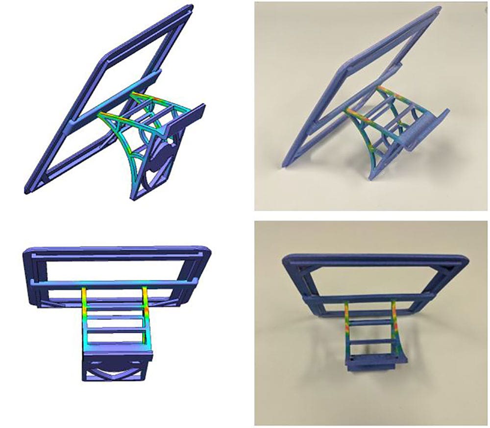
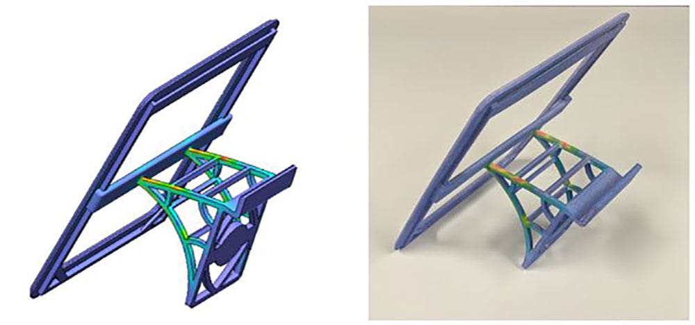
We can show you how with the HP MJF 580 3D printer and SOLIDWORKS Simulation! With the ability to 3D print in color, many new opportunities are available for design and engineering teams to take advantage of. 3D printed FEA models make great presentations and display pieces that provide a hands-on understanding of product performance under loads. In this blog, we are going to take a look at the steps involved in 3D printing a colored bracket overlaid with a static stress analysis map.
Setting Up the Study
To begin, open up your model in SOLIDWORKS and create a new static simulation study.
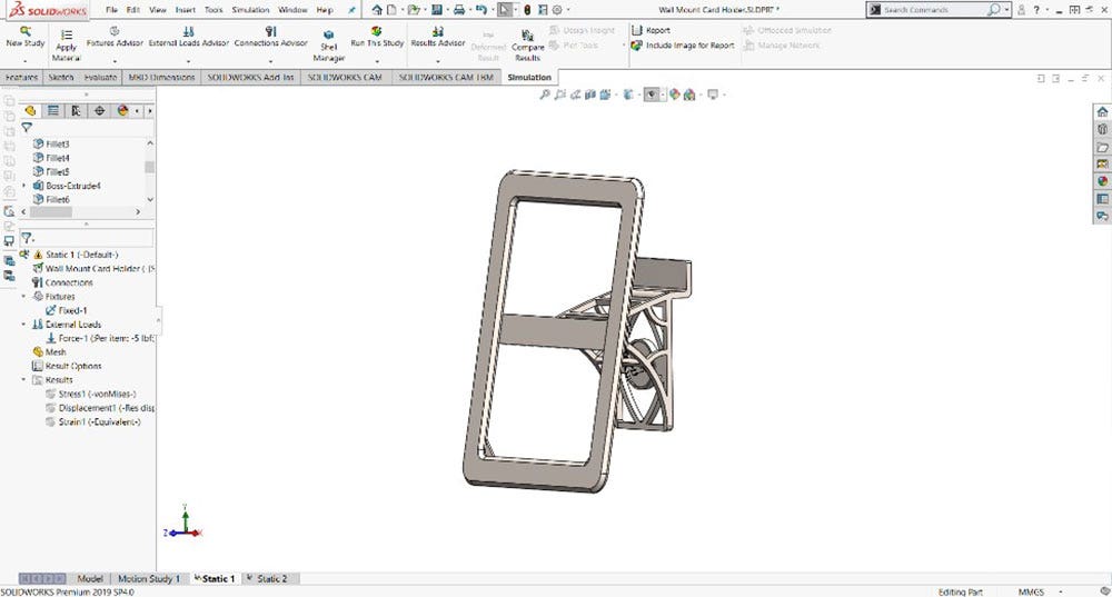
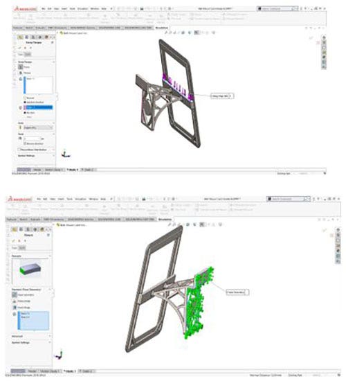
Set your boundary conditions by applying material, fixtures and loading conditions. Here we have applied a force load downward at the end of the bracket (shown in purple) to represent the force of an un-modeled component. Next, the back faces of the bracket (shown in green) were constrained to lock the bracket to a mounting surface.
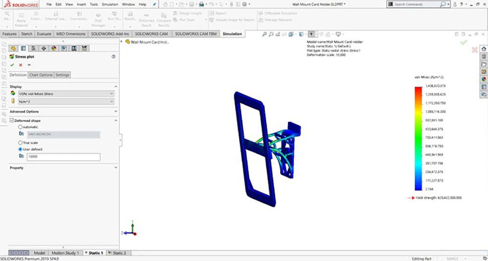
Running the Study and Selecting Results
Once your boundary conditions are all set, you are ready to run the study and review results.
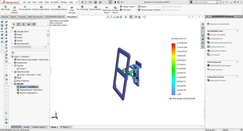
Now, you are presented a few commonly used plots but there are many more available to us:
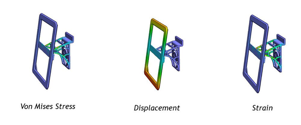
Do you want to 3D print stress results, displacement results or strain results?
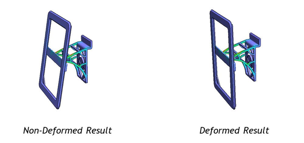
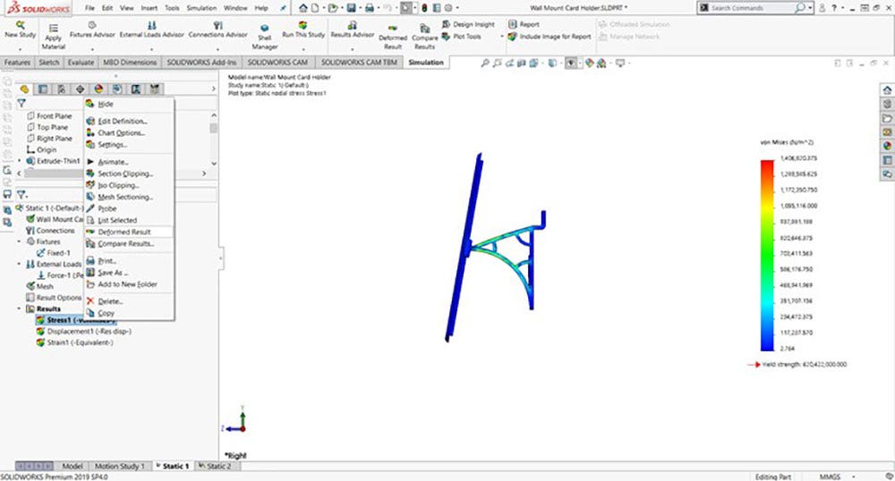
Do you want to print a deformed model that behaves as fully-loaded or do you want to print the stress map on an un-deformed model? In our example, we have toggled “Deformed Result” off in the drop-down menu to produce a Non-Deformed Result.
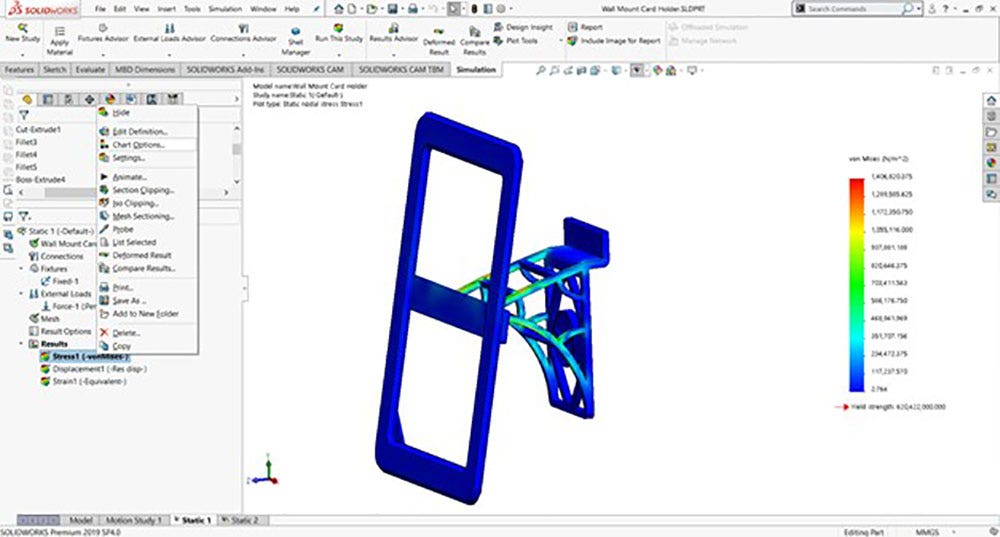
Exporting the Color Model
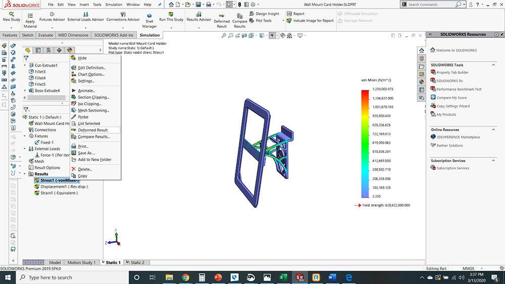
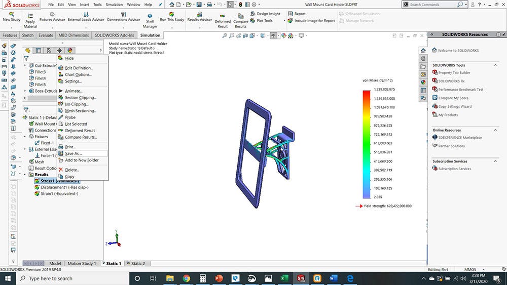
When you are happy with your study results, it is time to export the model. Select the plot that you want to export and then right-click “Save As.”
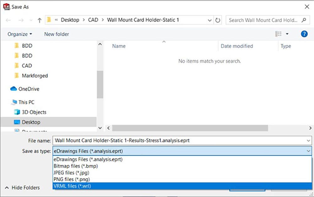
Use the drop-down menu to select the “VRML” file format. This file format carries surface geometry and model color from your CAD data.
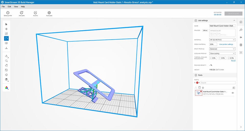
Importing the VRML File
Finally, import your VRML file into the HP 580 slicing software known as “3D Build Manager.” Once you verify that the model is showing the appropriate colors and the correct export, you are all set to print!
Using these tips and tricks, you will have everything needed to create your very own, full-color FEA prints!
 Additional Tips and Tricks
Here are a few more helpful tips in order to make the most of your designs.
Changing the Color Map Colors
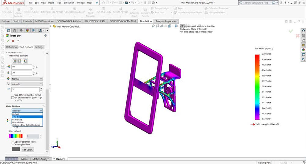
There are situations where you may want to change or create a custom color map for the part rather than stick with the standard color wheel. This is especially useful if you are looking to stick to specific color themes. To do this, right-click on your study results and then click on “Chart Options.”
Scroll down and open up “Color Options” to see your available color customization settings.
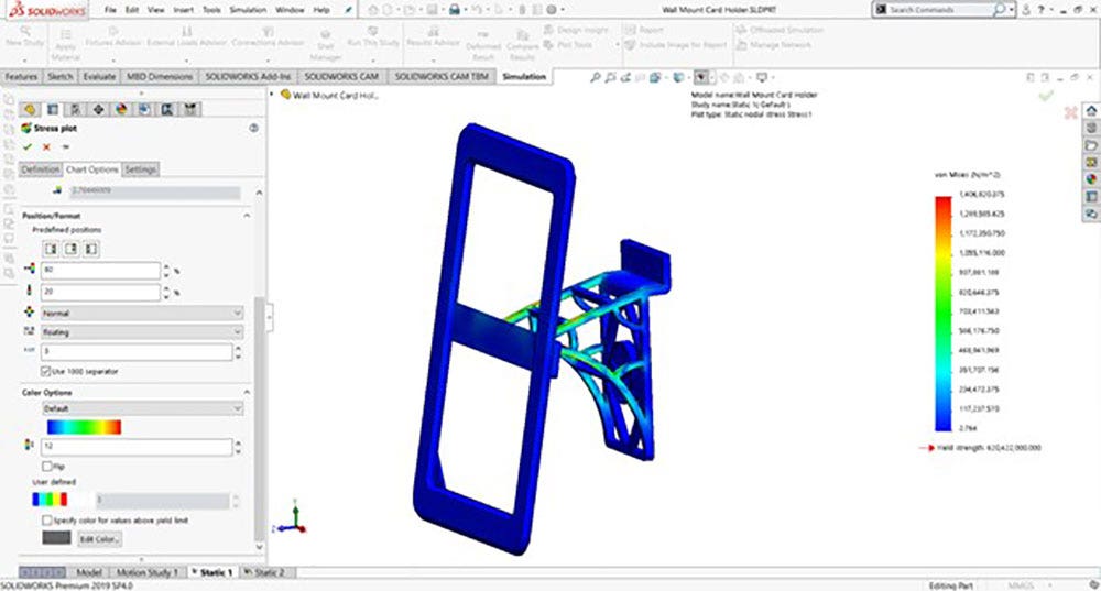
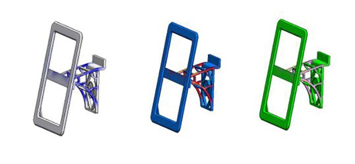
You can select from predefined themes or choose your own specific color options. “Rainbow” theme is shown below:
Custom color settings can be assigned to match your specific design needs!
Exaggerating Deformation Results
In many cases, there is a need to export deformed results. Many loading situations show a displacement that is too small to perceive upon visual inspection. To visually show how the part will deform, it is sometimes necessary to scale the deformation value. SOLIDWORKS has a standard deformation scale factor which can be manually edited by the user.
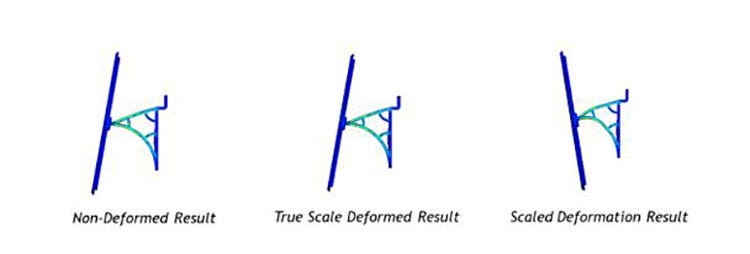
To access toggle your deformation view, select your desired results plot and then right-click to select “Deformed Result.”
To change the deformation scale, you can simply edit the definition of the plot with a right-click. Now you can change how much your results are exaggerated by using the “True Scale” (1:1), the “Automatic” (automatically scales the plot to it can be seen), or a “User Defined” deformation scale you can set exactly how you want.
Once you have selected your deformation settings, ensure that “Deformation Results” are showing. You can then export the file as “VRML” in the same way as before.
Visit our site for more information on the HP MJF 580 3D printer and if you have any questions, be sure to contact us at Hawk Ridge Systems today.