
So, you’ve successfully learned how to build your part and now you’re ready to create your first assembly. Congratulations!
Once you’ve inserted your components (via “Insert Components”, dragging and dropping, etc), let’s move on to mating. One of the great benefits of SOLIDWORKS is that there are multiple ways to accomplish the same result, and that also goes for mating!
We’ll discuss how we can use the Mates menu, Quick Mates, and SmartMates to get you up and running.
1. Mates Menu
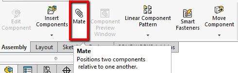
The first way we learn to mate is with the Mate icon (it resembles a paper clip) in the Assembly menu, on the CommandManager.
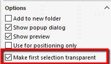
Once you’ve selected the Mate feature, you can select the first entity to mate. It also may turn transparent, if ‘Make first selection transparent’ is turned on the very bottom.
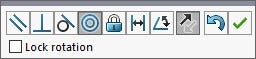
Next, select the second entity you want to mate to. Based on the selections, SOLIDWORKS will guess which mate you’re trying to create. If it’s the correct one, press the green check to accept it; if it isn’t, select the mate you’re looking for and accept it.
TIP: Use the Alt key to temporarily hide a face when you need to select through it.
In some instances, certain mates will require you to select the mate first, before selecting the entities to mate, such as the Width mate under the Advanced Mates.
2. Quick Mates
Another way is to pre-select the faces you’re creating a mate for, without having to be in the Mate menu. Simply hold down Ctrl and select the two entities you wish to mate.
The supported mate types are all standard mates (Concentric, Coincident, Equal, etc), as well as some advanced mates (Profile Center, Symmetric, and Width) and some mechanical mates (Cam and Slot).
3. SmartMates
If you prefer to drag your components together and have them magically snap into place, SmartMates is probably more up your alley.
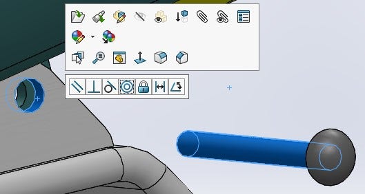
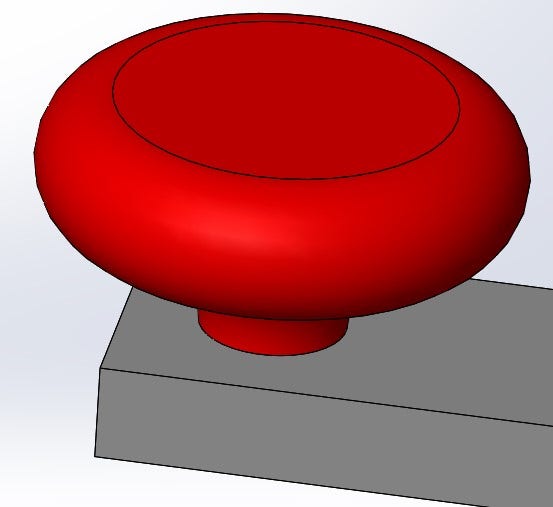
In this scenario, we’ll create a ‘peg-in-hole’ SmartMate, which will result in a concentric and coincident mate.
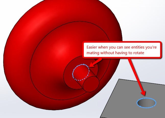
To create it, hold down the Alt key, and left-click and drag the circular edge to the edge you want to mate it to. If successful, you’ll see this icon:
![]()
TIP: It’s easier when you can see what you’re dragging and what you’re dragging it to, in the same view.
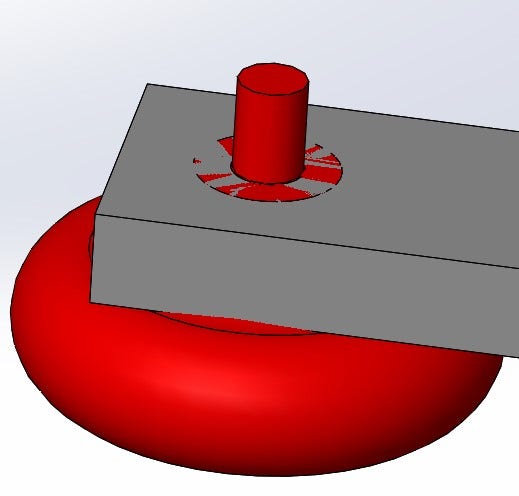
2 Options If Your Part Flips
If the part flips on you, there are two options to fix it:
1. If you have let go of your left mouse button (release the part), click the Tab key to flip the orientation.
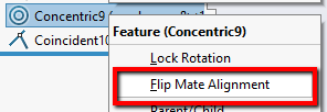
2. If you haven’t released your left mouse button, right-click on one of the mates that’s created and select Flip Mate Alignment.
Here’s a breakdown of different types of mates that can be created when using SmartMates:
| Pointer Mating Entities | Type of Mate |
|---|---|
| 2 linear edges, or 2 temporary axes | Coincident |
| 2 planar faces | Coincident |
| 2 vertices | Coincident |
| 2 conical faces, or 1 conical face and 1 temporary axis | Concentric |
| 2 circular edges (peg-in-hole SmartMates). The edge do not have to be complete circles. | Concentric (conical faces)and Coincident (adjacent planar faces) |
| 2 circular patterns on flanges (flange SmartMates) | Concentric and coincident |
| Origins and coordinate systems | Coincident |
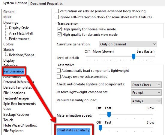
Lastly, if you want to control the speed that SOLIDWORKS applies the SmartMate, that can be done in the System Options > Performance > SmartMate Sensitivity. Dragging the slider from left to right will decrease the speed of the SmartMate.
For more information on SOLIDWORKS or if you have any questions, don’t hesitate to contact us at Hawk Ridge Systems today. Thanks for reading!


