This blog and accompanying video series will illustrate some very simple methods for creating a basic parametric bookcase that is easily configurable into many shapes and sizes with minor adjustments to just a few dimensions. In Part 1 we will create the bookcase using Top-Down Assembly Modeling technique. Part 2 will use a multi-body part environment to create the book case, and utilize the cut-list generated from the Weldment Feature. The concepts that will be discussed are basic but will illustrate some very powerful techniques using SolidWorks.
This project initially came about when I was asked to create a basic model of the floor plan of one of our offices. The plan was to expand our office space by knocking out some walls and renovating the space with new carpet, paint, and trim. From a simple floor plan I modeled up a rendition of the basic office space with the new expansion. In order to get some perspective of size with the space, I needed to create some basic furniture like desks and book cases to place in the modeled office environment. The following is how to create the book case using Top-Down Assembly Modeling Technique.
I begin the bookcase with an Assembly template and create a 3D Sketch on the top plane, centered on the origin. I have created a video called ‘3D Sketch Basics’ that demonstrates how to create a similar sketch. (Click the link to watch 3D Sketch Basics here: https://www.youtube.com/watch?v=ChhM7JJ_GIY). Notice that the sketch for the bookcase is all construction geometry, and the dimensions have names that represent Length, Height, and Depth of the bookcase. As can be seen in the image at left, I have created global variables representing the material thicknesses for the top and case panels.
 |
 |
 Now that the size of the book shelf is defined by the 3D sketch, I can begin inserting New Parts into the assembly constraining them to the 3D sketch. For Top-Down Assembly modeling, new parts are created within the context of the assembly. From the Assembly Command Manager tab, choose Insert Components and New Part from the drop down. In my book case, I choose to model the left side panel first, then the right. Each panel will become a new part in the assembly by following these steps. When inserting a new part into an assembly I need to select a face or a plane in the assembly that will be mated to the FRONT plane of the new part being inserted. For the left side panel, I chose the Top Plane of the assembly. This will create an InPlace mate between the Top Plane of the assembly and the Front Plane of the newly created part.
Upon creation of the New Part within the context of the assembly, several things happen at once:
- A new virtual part is added to the feature manager tree of the assembly.
- An InPlace mate is created between the selected Face or Plane of the Assembly and the Front Plane of the newly created part.
- The SolidWorks environment changes from Editing Assembly to Editing Part Mode.
- A sketch is created and opened on the Front plane of the newly created part and the environment changes further to Editing Sketch.

In the image above, you can see that I created a rectangular sketch that is coincident to the sides of the bottom of the 3D sketch with a thickness dimension that is utilizing the Global Variable Panel Thickness previously created in the assembly. I then extruded the new part using an Up to Vertex end condition thereby tying it to the top of the 3D sketch. The right side panel is created using the same process.
The next panel to create is the top. Using the same process of inserting a new part outlined above, I chose the top edge face of one of the side panels and created the sketch illustrated in the image below. As seen in the image, the sketch is dimensioned with the appropriate overhang relief for the side and front with a proper radius on the corner features. I then extruded this panel up with a dimension being driven by the Global Variable Top Thickness.
 |
 |
Notice the image of the Feature Manager Tree above. The blue text of the Top component signifies that it is being edited within the context of the assembly. To the right of each of the components name is an arrow “->”. This indicates that the components have external references (the assembly they are being created in). As each component is created in the assembly, SolidWorks gives them a default name and are considered a Virtual Part.
 In other words they only exist in the assembly and have no actual file on disk. If you right click on the name of the component in the Feature Manager Tree you will have commands available from the contextual menu to Rename Part and to Save Part (in external file). I have done both selections for each panel as I create them, to ensure that I have separate part files for each panel saved to disk.
Working my way through each panel one at a time, I created the back panel next. The selection face for this part is a vertical edge face of one of the side panels. Using a standard rectangle I constrain the panel to the inside corners of the side panels and the 3D sketch, and extrude the panel towards the interior of the case being driven by the Panel Thickness Global Variable.
The Front Stringer is created next. With this part I chose the inside face of the left side panel for the placement of the stringer part, created a rectangular sketch positioned in from the front edge of the side panel .25” and a height of 2”. The thickness dimension for the part uses the Panel Thickness global variable. The sketch is then extruded with an Up To Surface end condition to the inside face of the opposite Right Side Panel.

Now that the basic framework of the case is complete it is time to account for the shelves. For the bottom shelf, I chose the top edge face of the Front Stringer as the placement plane for the Bottom Shelf component. A corner rectangle is sketched with coincident relationships to the inside of the existing side and back panels with a single set back dimension for relief from the front edge of the side panels. The panel extrusion dimension is driven by the Panel Thickness Global Variable. I then added a simple cut to the front edge of the panel to give a rounded detail. Notice the images below.
 |
 |
The adjustable shelf I created a bit differently. Since it is to be adjustable, I needed to choose a plane in the assembly that would allow for movement of the panel. I chose the Front Plane of the Assembly as the placement plane for the Adjustable Shelf. Notice in the image below, I created a rectangle on the Front Plane and extruded both directions with Offset from Surface end conditions to account for clearance for the shelf within the book case.

I would like to draw your attention to something in the image above. There are holes on the inside face of the side panels. These are for adjusting the shelf. There were created as a pattern of holes then converted to a Design Library Feature Part. (I will create a separate blog and video to show how this is accomplished for this series…Stay Tuned!!). If you notice, I created one adjustable shelf part and then pattern that in the assembly. Notice the bottom line of the panel sketch has 2 sketch points. These are related to the center points of the holes in the Right Side Panel for positioning purposes. After I created the side panels, I edited them individually and placed the shelf holes as well as a rounded detail feature on the front edges of each of the side panels.
 Another tidbit that needs mentioning is the use of Assembly Level Global Variables. If you are editing a part within the context of an Assembly (Edit Part Mode), Assembly Level Global Variables will not be available. If you double click a feature of a part while in Editing Assembly mode, double click a dimension, and press “=” in the Modify dialogue, then the Assembly Level Global Variable will be available, as shown in the image at right.
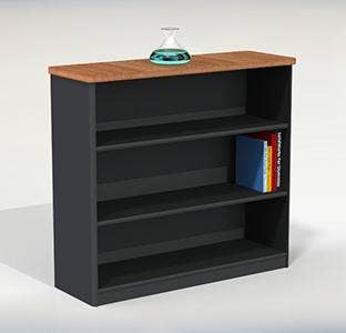
Examine the Feature Manager Tree for the assembly in the image above. All of the panels have the arrow next to them signifying they are referencing the assembly. Each part, except for the Stack of Books and the Glass Vase, have all been created within the context of the assembly. THAT is Top-Down Assembly Modeling! As you can guess, any changes made to the dimensions shown from the 3D sketch will drive all of the sizes of the panels.
This assembly actually has 3 configurations to it. Each of the side panels have configurations that vary the hole-pattern for the adjustable shelves to match the 3 configurations of the Assembly. In addition, the top level assembly has configurations that vary the size dimensions and the pattern instance count of the pattern of adjustable shelves (located at the bottom of the tree shown above). The result is a very flexible system of shelves that represent the sizes in our office that I now can use in the office model.
Stay tuned for more blogs and videos in this series. Topics covered will be Multi-Body Part Design, Library Feature Parts and Configurations!
 |
 |
 |


