

If you are using linear patterns in your sketches, I’ve got some exciting news for you! There have been some great enhancements with the release of SOLIDWORKS 2022. Now, you can use a line as a direction reference (previously it would become part of the patterned entities). Also, you can pattern and copy text in linear patterns.
I’m working on a plane propeller here and I want to add in some features for manufacturing. I already have a couple of sketches that I’m going to use for the features.
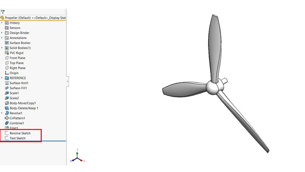
Propeller and Sketches
The Revolve Sketch is going to be a revolved cut for mounting the propeller. I have a construction line at a 3-degree angle and a square because that is the shape and orientation that I need for this mounting feature.
Using a Line as a Direction Reference
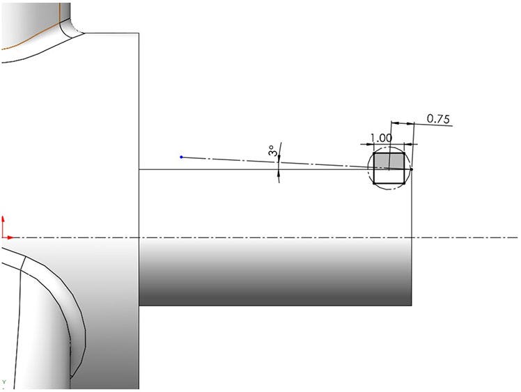
Revolved Feature Sketch
To start a linear pattern, click on the Sketch command manager tab and select the command.

Linear Sketch Pattern command
The default is the X-axis as the direction for the pattern, but I can use my construction line instead! This is helpful when your pattern doesn’t follow X and Y directions. I’ll specify spacing and instances to add a couple more squares and then create a revolved cut.
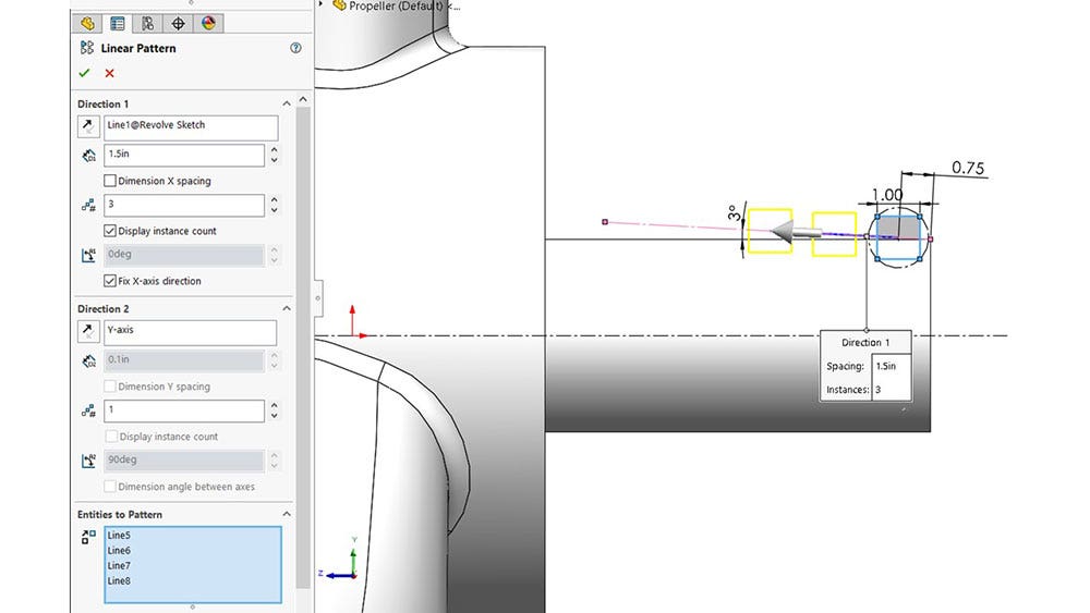
Sketch settings
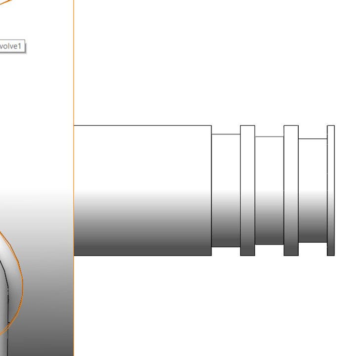
Finished Revolved Cut
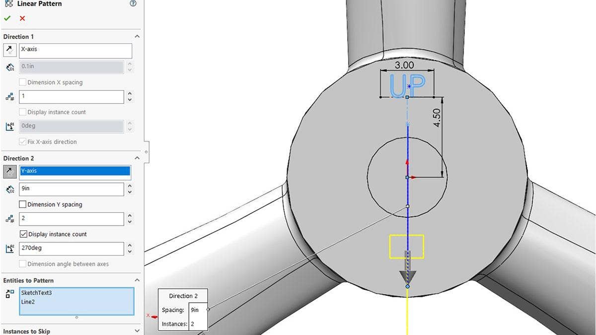
Next, I want to add some text for the installers so that they know which way is up when they are mounting it. The Text Sketch has some construction geometry and the word “UP” in it, but I also want to put it on the bottom of the face. Instead of doing more construction geometry and text, I’ll use the linear pattern again.
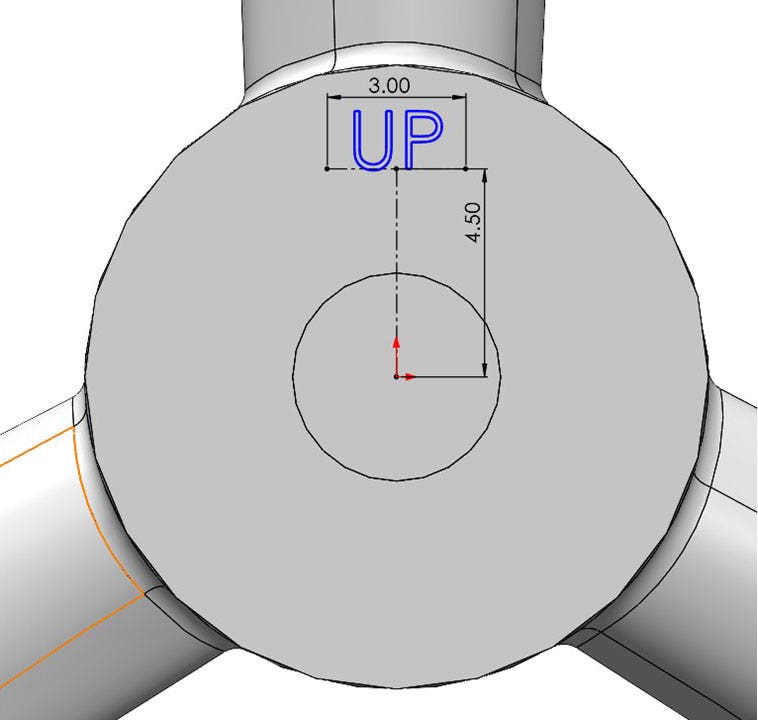
Sketch with Text
This time, I could use the Y-axis as the pattern direction but I’ll just use this vertical construction line as I did in the previous sketch. I’ll put in the spacing and instances and flip the direction, then create a cut for the feature.
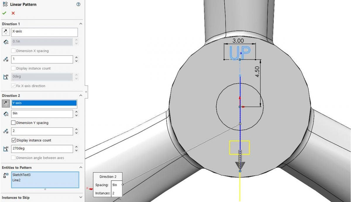
Text Linear Pattern
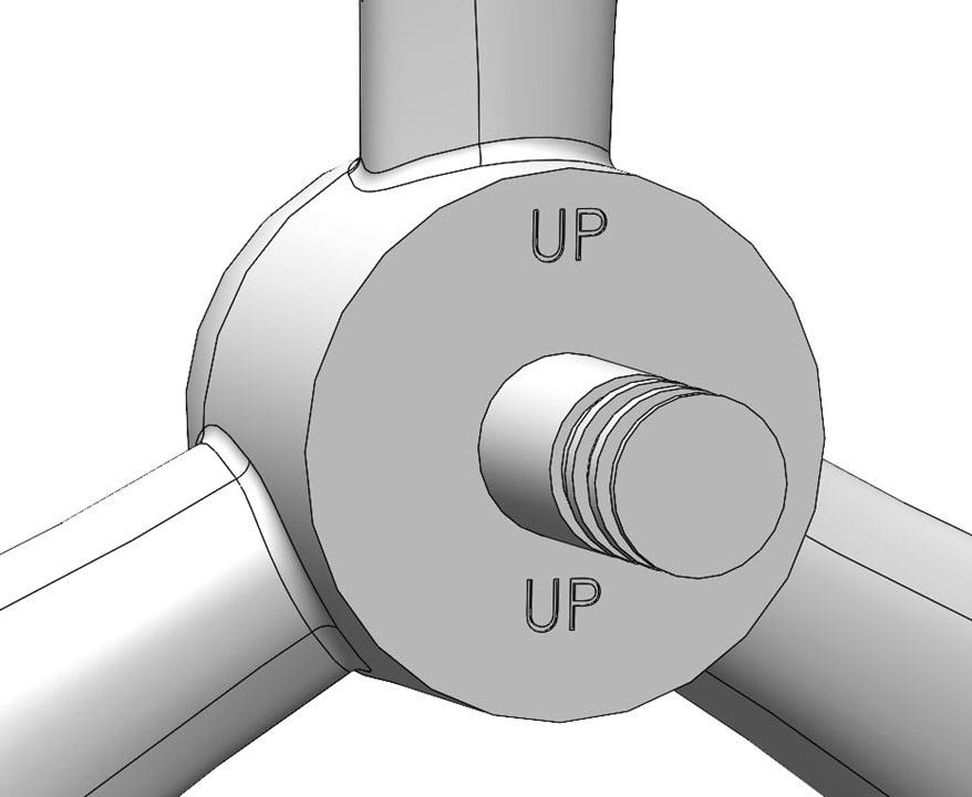
Cut using Text
Hopefully, this blog showed you some useful and time-saving ways to use linear sketch patterns in SOLIDWORKS. If you’d like to learn more or if you have any questions, please contact us at Hawk Ridge Systems today. Thanks for reading!
Put your next design into motion
Explore solutions and expert guidance for your application.
Ask an Engineer
Written by Vince Farrell
Vince Farrell is an applications engineer with a design background in the LED industry. He has over four years of SOLIDWORKS experience in both LEDs and aerospace industries. In his spare time, Vince likes to spend time with family and friends, hit the gym, and travel.