Have you ever hoped that one day, there would be a way for you to utilize your
3rd party CAD data into SOLIDWORKS without having to go through the
process of saving it out as a STEP file or some other neutral format?
SOLIDWORKS 2017 has introduced a step in that very direction with 3D
Interconnect! In this 3 part series, we’re going to explore 3 workflows we’ll
see 3D interconnect best utilized:
-
To directly insert the 3rd party CAD data into SOLIDWORKS
assemblies to be used to mate and design around like any other SOLIDWORKS
component. -
To be opened as a base/derived part so we can add native SOLIDWORKS features
to the existing 3rd party design data. -
To perform feature recognition on the 3rd party design data, and
break the link to the party while still preserving faces and edge ID’s.
In this initial blog, we’ll explore how to turn on 3D Interconnect, see what
formats we’ll be able to import, as well as one of the main workflows on how
3D Interconnect will most likely be used.
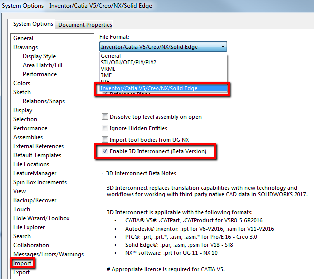
To be able to utilize 3D Interconnect, we want to access the ‘Import’ options
through ‘System Options’. While in the ‘Import’ Menu, we’ll want to change the
‘File Format’ to ‘Inventor/CATIA V5/Creo/NX/Solid Edge’. Once selected, we’ll
want to make sure ‘Enable 3D Interconnect’ is checked!
 |
What are some of the formats 3D Interconnect can work with, you ask? Here they
are:
-
PTC
- .prt, .asm for Pro/E 16 – Creo 3.0
-
Autodesk Inventor
- .ipt for V6 – 2016
- .iam for V11 – 2016
-
Solid Edge
- .par, .asm, .psm for V18 – ST8
-
Siemens NX
- .prt for UG 11 – NX 10
-
CATIA V5 (SOLIDWORKS Premium)
- .CATPart, .CATProduct for V5R8 – V5R2016
One of the main ways we see our customers utilize 3D Interconnect is directly
importing an assembly or part file from their 3rd party CAD data
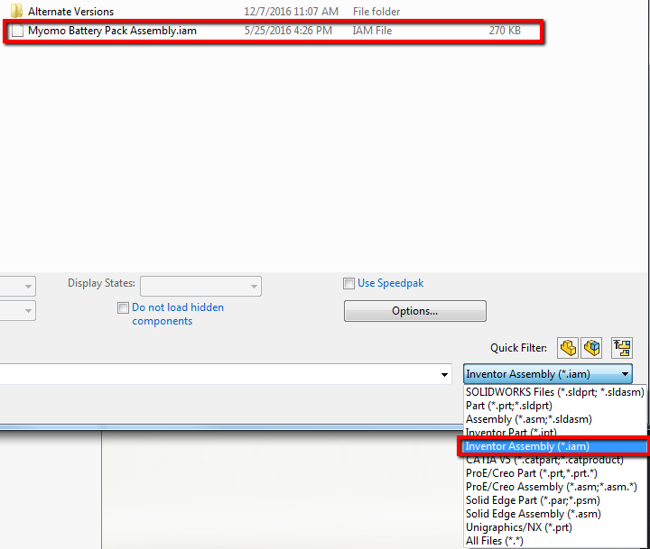
right into their SOLIDWORKS assembly. SOLIDWORKS has simplified the workflow
down to just doing an ‘Insert Component’ and either selecting ‘All Files’ as
the ‘File Type’ to show or the specific file type you’re looking for. In this
case, we’ll bring in an AUTODESK Inventor Assembly file (.iam)
 |
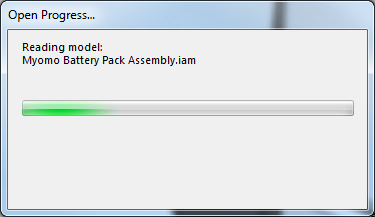
Afterward, we’ll see this ‘Open Progress’ dialog box to tell us SOLIDWORKS is
reading the model.
 |
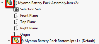
Once brought in, we can see the FeatureManager will include a green arrow on
the assembly and part icons to indicate it was imported from a 3rd
party CAD program.
 |
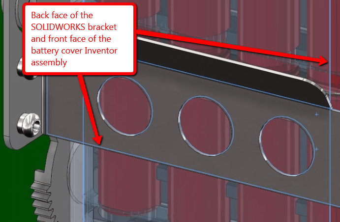
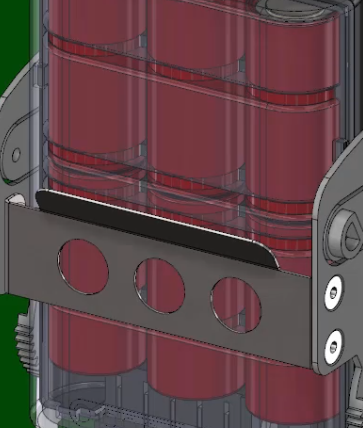
From here, we can treat the Inventor assembly like any other SOLIDWORKS
assembly by creating mates to the existing SOLIDWORKS geometry to properly
place the battery pack into position.
 |
Now, say a different version of the battery pack has been created in Inventor
and we want to utilize that in our SOLIDWORKS assembly, while still preserving
all the assembly mates we used to position it. It’s almost as easy as
importing it in! First, you’ll want to overwrite the existing Inventor
assembly through Windows Explorer. After doing so, if you take a look at your
FeatureManager tree, we’ll see a small refresh icon by the assembly icon. To
update the model, we’ll simply right click and select ‘Update Model’. The
mates will update automatically to correspond to the new geometry!
 |
By utilizing this workflow, we can open propriety 3D CAD data directly into
SOLIDWORKS while retaining associativity to the original file! This allows
you, as the engineer or designer, to work more seamlessly with your other CAD
data! Stay tuned for Part 2 of the 3-part series where we’ll explore how 3D
Interconnect can integrate CREO files into our SOLIDWORKS assembly!
 |
For more information, check out our
YouTube channel
or contact us at
Hawk Ridge Systems
today. Thanks for reading!
