Hi everyone and welcome, welcome, welcome again to another blog from me! In
this article, I’m going to cover something that is pretty near and dear to me.
It’s called a revision table and it’s something that I used to create manually
on my drawings. Thankfully, SOLIDWORKS has a great feature to do this for us.
I will go over the basics to use revision tables in your own drawings.
The example that I’m going to use is a drawing of a piston head for an RC car
that I’m working on. I have some standard views, along with a section view and
a couple of detail views.
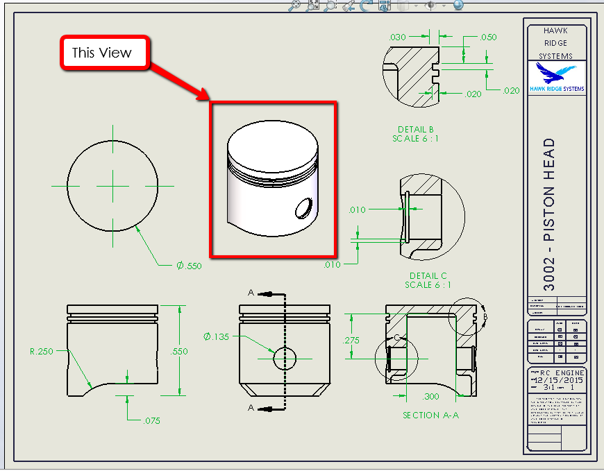
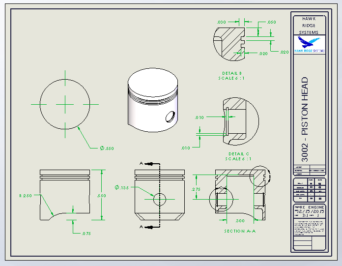 The RC car piston head drawing includes standard views, a section view, and several detail views. The RC car piston head drawing includes standard views, a section view, and several detail views. |
I’m going to make a change to the part, and I want to make sure it opens up in
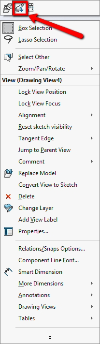
this isometric view, so I’ll right click on the isometric view and use a
function that was introduced in SOLIDWORKS 2015,
open part in position. That opens the part in the exact
orientation that I was looking at in the drawing.
I want to make these grooves bigger, so I’m going to double click on the
feature to expose the dimensions, and then double click on the 0.020 inch
dimension to edit it. I’ll change that to 0.030 inches and rebuild it so that
the change is applied. Now I’ll switch back to the drawing and I can tell in
DETAIL B that the change has been applied.
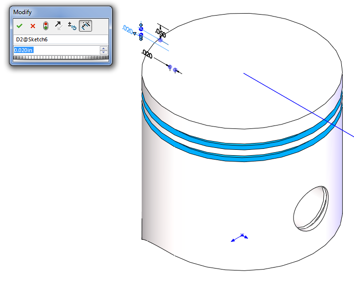 Editing the groove dimension from 0.020 to 0.030 inches and rebuilding applies the design change. Editing the groove dimension from 0.020 to 0.030 inches and rebuilding applies the design change. |
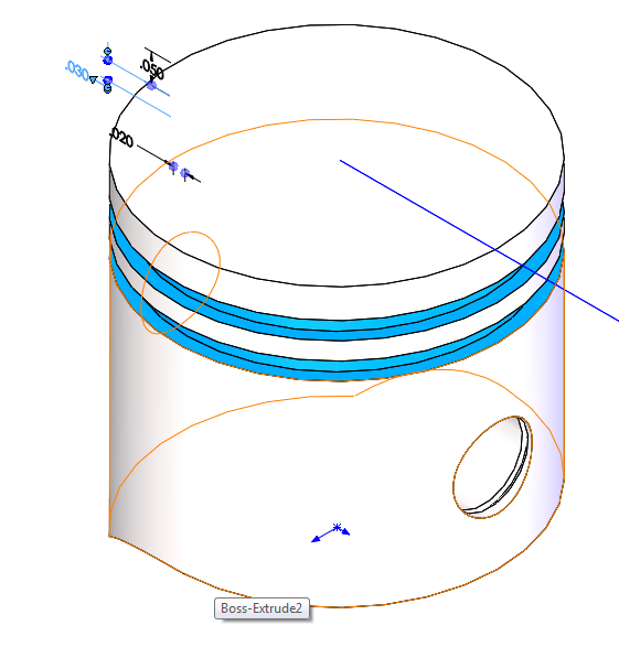 Rebuilding after the dimension change updates both the part and its linked drawing views. Rebuilding after the dimension change updates both the part and its linked drawing views. |
This part is already being made, so I need to add in a revision table. In the
Annotation command manager, all the way at the end, are the tables. There are
a lot of standard tables to use, but the one I want is the revision table so
I’ll select that.
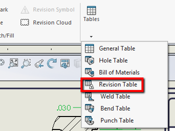 The revision table is added from the Annotation command manager, alongside SOLIDWORKS’ other standard tables. The revision table is added from the Annotation command manager, alongside SOLIDWORKS’ other standard tables. |
Once I do that, the property manager opens up on the left and I have many
options to choose from. A default table template is shown, but this can be
customized and saved. If the drawing has an anchor point, I can have the table
snap to that with this option. I can also change what symbol I want to use for
the flags. The circle is shown, but since I usually use this for item numbers,
I’m going to use the triangle. Down at the bottom, I can customize the border
and drawing layer of the table.
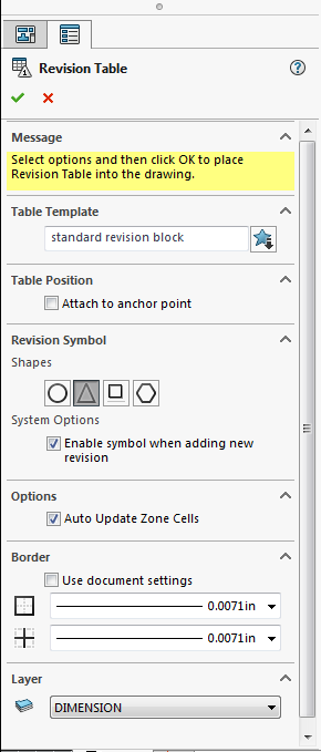 The revision table’s PropertyManager lets you snap it to an anchor point, choose a symbol, and save a template. The revision table’s PropertyManager lets you snap it to an anchor point, choose a symbol, and save a template. |
I’m going to hit the green check to place the table into the drawing. Just
like other tables in SOLIDWORKS, this table is fully customizable with options
that are similar to the ones in Microsoft Excel. These are the columns in the
default template, but I can add or delete any by right clicking on a header
and hovering over Insert. You don’t need to do that to add a row for a
revision, though, just click on the symbol at the bottom left-hand corner. You
need to hover over the table after it’s placed to get this symbol.
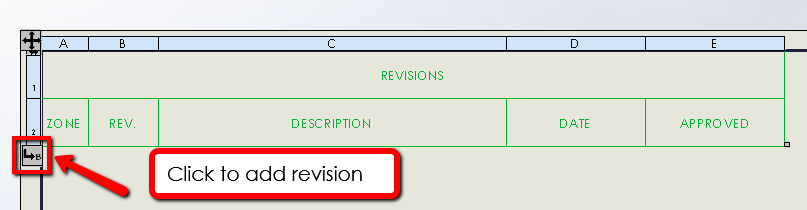 Once placed, the revision table’s columns can be added or deleted by right-clicking, much like an Excel table. Once placed, the revision table’s columns can be added or deleted by right-clicking, much like an Excel table. |
Once a row has been added, the revision is numbered per the table properties
and the date is automatically added. The flag note is next to your cursor and
ready to be placed down. I will put it next to the changed dimension.
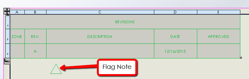 Adding a row auto-numbers the revision and stamps the date, with a flag note ready to mark the change. Adding a row auto-numbers the revision and stamps the date, with a flag note ready to mark the change. |
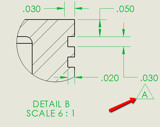 The flag note follows the cursor until placed, marking exactly where the drawing change occurred. The flag note follows the cursor until placed, marking exactly where the drawing change occurred. |
I can put in any additional flags as needed and just hit
Escape on my keyboard to stop placing notes. Now it’s time
for me to type in a description, so I’ll double-click in that field and type
in, “Changed 0.020” to 0.030”.” Hit the green check to accept the text.
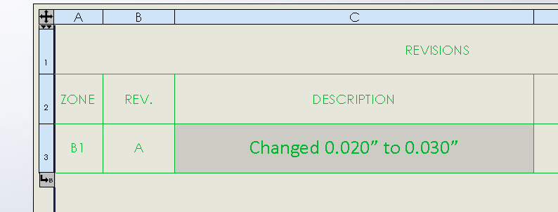 Typing a description like the dimension change into the revision row completes that entry. Typing a description like the dimension change into the revision row completes that entry. |
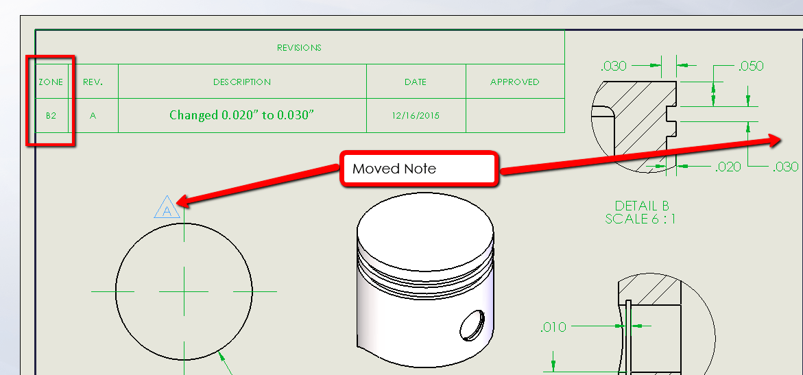
Notice now that there is a B1 in the Zone column. This corresponds to where I
put the flag note.
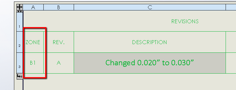 The Zone column automatically fills in, here showing B1 for where the flag note was placed. The Zone column automatically fills in, here showing B1 for where the flag note was placed. |
If I move the note across the drawing, the zone changes to match.
Additionally, if I put in another flag note, all of the locations will be
listed.
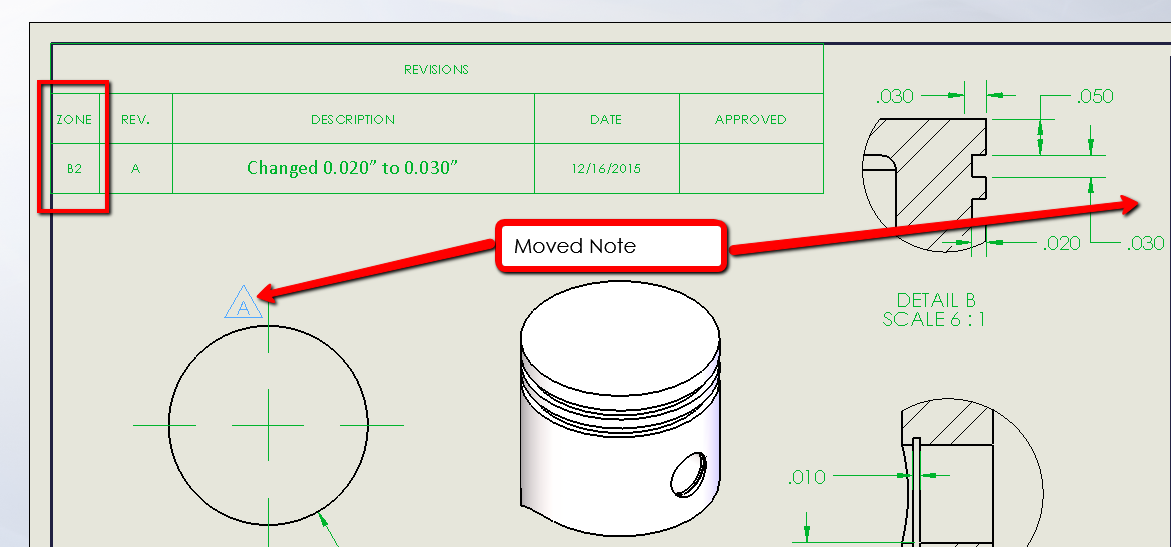 Dragging the flag note to a new spot on the drawing updates its zone entry to match automatically. Dragging the flag note to a new spot on the drawing updates its zone entry to match automatically. |
On the annotation command manager, click the
Revision Symbol button and place down as many more notes as
you need.
 The Revision Symbol button on the Annotation command manager places additional flag notes as needed. The Revision Symbol button on the Annotation command manager places additional flag notes as needed. |
Where is it getting that zone information from, you ask? Great question and to
answer that, let’s switch to the Sheet Format (here’s a link to my blog on Sheet Formats in case you need it). Right click in the blank area and select Automatic Border.
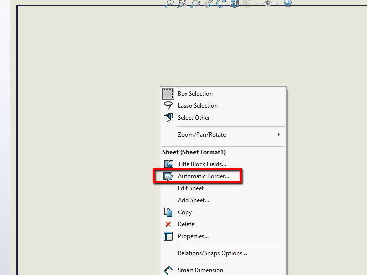 Zone data for the revision table comes from Automatic Border, set up under the drawing’s Sheet Format. Zone data for the revision table comes from Automatic Border, set up under the drawing’s Sheet Format. |
This brings up the automatic border property manager, and by hitting the next
arrow at the top, we can see the zone lines and margins. From the preview, I
can see that the borders will interfere with my current template, but that’s
okay for now. I’ll hit the green check, and go back to the sheet so that you
can see the regions.
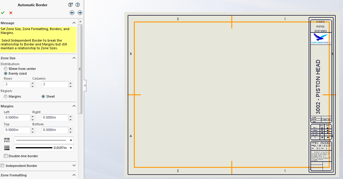 The Automatic Border preview shows zone lines and margins, even where they conflict with the existing template. The Automatic Border preview shows zone lines and margins, even where they conflict with the existing template. |
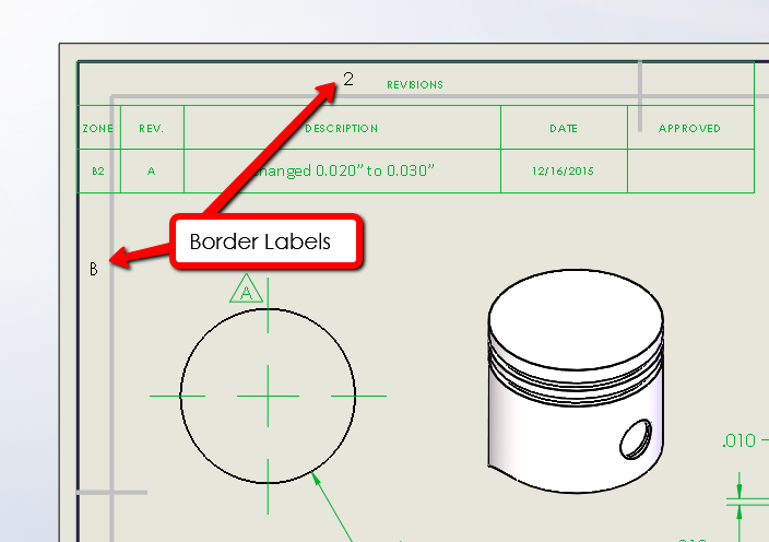
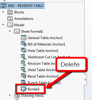
Now that they are displayed, the flags make sense. To get rid of that, just
expand the Sheet format and delete the Border feature.
After all that, I can add in more revision rows by simply clicking the icon in
the lower left of the table just like putting in that first revision. I really
hoped you enjoyed this article on adding and modifying your own revision
tables. For more information, check out our
YouTube channel
or contact us at
Hawk Ridge Systems
today. Thanks for reading!