
How to Extend Features from Sketch Plane to Create Powerful Geometry in SOLIDWORKS
“Extruded Boss” may be one of the most used commands in SOLIDWORKS, but are you familiar with all the available end conditions and how to use them? If you’re designing hold down fixtures, as one example, the “Up to Surface” end condition can come in handy. “Up to Surface” simply extends features from the sketch plane to a surface you select. In this short SOLIDWORKS tips and tricks article, we’ll show how to use the “Up to Surface” end condition and some examples of the powerful geometry we can quickly create with it.
Where is “Up to Surface” in SOLIDWORKS Used?
The “Up to Surface” end condition is available in many different features, such as Extruded Boss, Extruded Cut, and Extruded Surface. For consistency, we will focus on how to use it with the Extruded Boss command here, although the setup is similar for all commands where the condition is available.
How to Use the Up to Surface End Condition in SOLIDWORKS
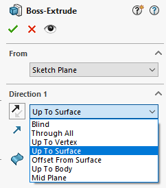
The “Up to Surface” end condition can be selected in the drop-down menu for Direction 1 (and Direction 2, if applicable) after the extrusion is started.
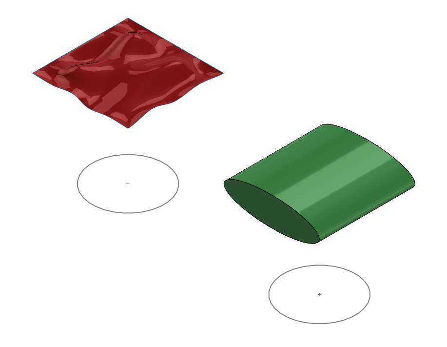
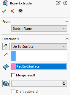
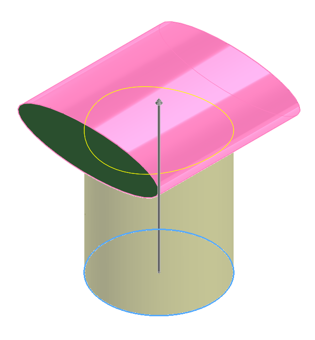
Then, the terminating surface or face is selected for the pink selection box. Ideally, this surface/face should be larger than the extrusion profile. Otherwise, SOLIDWORKS will attempt to automatically extend the terminating surface for the full profile, but this only works on analytical surfaces/faces.
The merge result checkbox will merge the extrusion with the terminating body when a face of a solid is selected, but when terminating at a surface body it will have no effect.
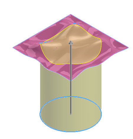
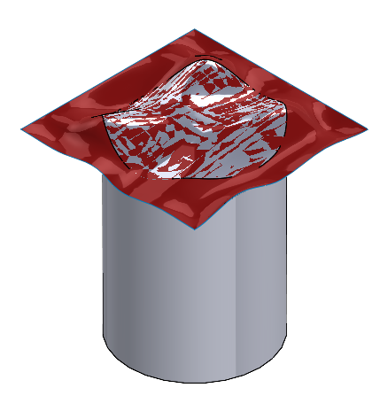
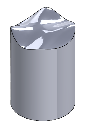
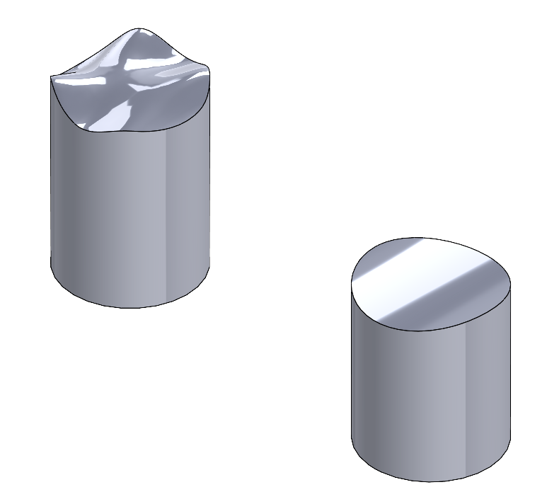
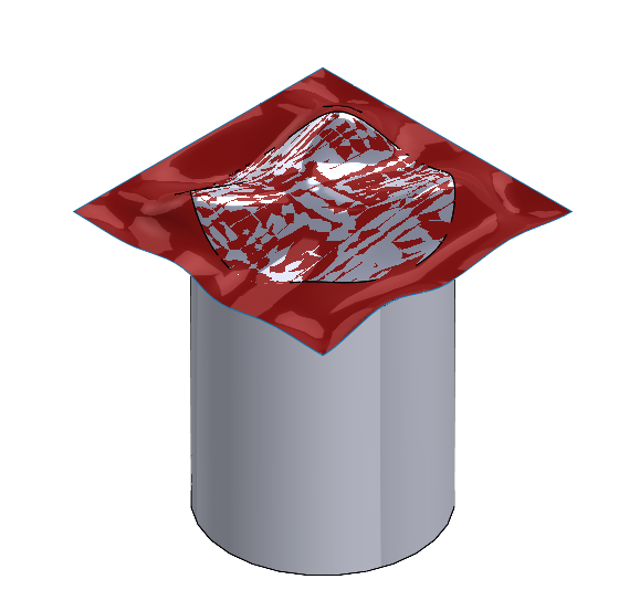
After clicking ok, the resulting extrude will overlap with the surface. The mottled appearance is a result of small approximations in the display that SOLIDWORKS uses when two items occupy the same space. If it won’t be used again, the surface can be hidden or deleted.
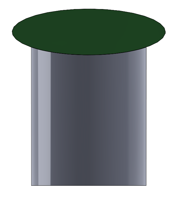
For the green ellipse, the process is similar. Simply select the outer face of the ellipse shape as the terminating surface/face. The “Merge result” checkbox is left cleared.
Comparing Up to Surface with Cut with Surface in SOLIDWORKS
Similar functionality can be achieved with the “Cut with Surface” command, but which is better? As always, the answer depends on design intent. This tool is located under Insert>Cut>With Surface. Unlike the “Up to Surface” end condition however, this command cannot accept a face. It must be a surface or plane.

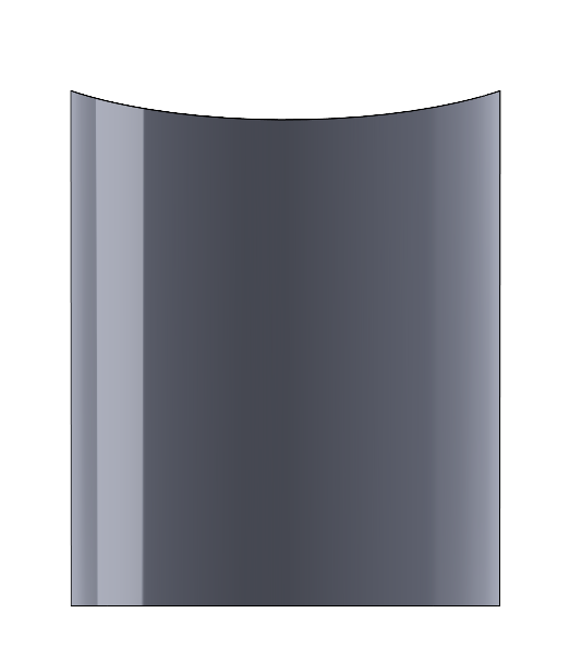
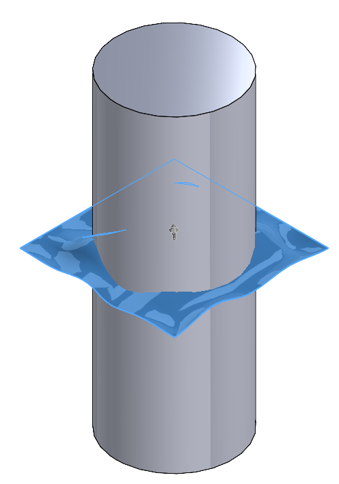
Here, the circular sketch is extruded past the red surface.
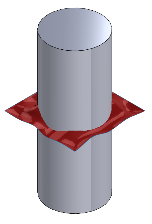
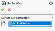
The command is activated, and only one selection is available. The red surface is selected as the cutting tool.
The arrow in the PropertyManager or in the graphics area indicates which side of the surface will be removed.
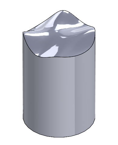
After clicking ok, the result is identical. The surface can then be hidden or deleted if necessary.
Putting it all together: Up to Surface and Cut with Surface in SOLIDWORKS
Both the “Up to Surface” end condition and “Cut with Surface” tool are powerful features we can leverage in SOLIDWORKS to add more complex geometry to our models with relatively little effort. While this could be useful in a variety of different situations, one common example that comes to mind is designing hold down fixtures, as custom shaped tooling can be created based on the surface geometry of the part being fixed. Remember that the “Up to Surface” end condition can accept a surface or face as input, while the “Cut with Surface” command can accept a surface or plane.