Spreading Holiday Cheer with Hawk Ridge Systems
I have designed myself a catapult with some specific design criteria in mind with the intent on spreading holiday cheer through the office. I will be firing a Hawk Ridge Systems present to all of my coworkers!
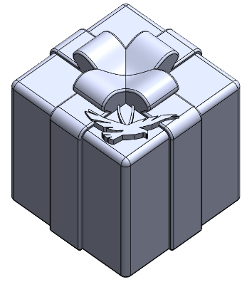
The catapult is going to be 3D printed and shipped to me so I want it to be a flatly packed assembly that can be assembled without any fasteners to hold it together. I am going to be using a Markforged printer so I am going to keep my design inside of a cubic foot design space and don’t want to exceed a material volume of 8 in3.
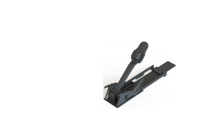
The above image is a render of the final design but before I go physically prototyping I want to use SOLIDWORKS Simulation to validate the strength of the parts.
Strength of Parts
The areas where I am worried about structural integrity are on the two components that are impacting each other, the arm and stopper. For simplicity sake, I will ignore the dynamic effects and reduce the simulation to the maximum torque that the spring can apply. The Markfordged printing process generates a material that is orthotropic with the vertical direction having different material properties than the directions planar with the print bed. SolidWorks has the capability to simulate orthotropic materials but for simplicity sake, I will assume an isotropic material as the printing orientation will be chosen to optimize material properties in the loading directions. Since SOLIDWORKS does not have the Markfordged ONYX material I had to create a custom material based on the properties listed online.
This is done in the edit material command. You can copy and existing material and manipulate the properties or create one from scratch as you can see in the image below.
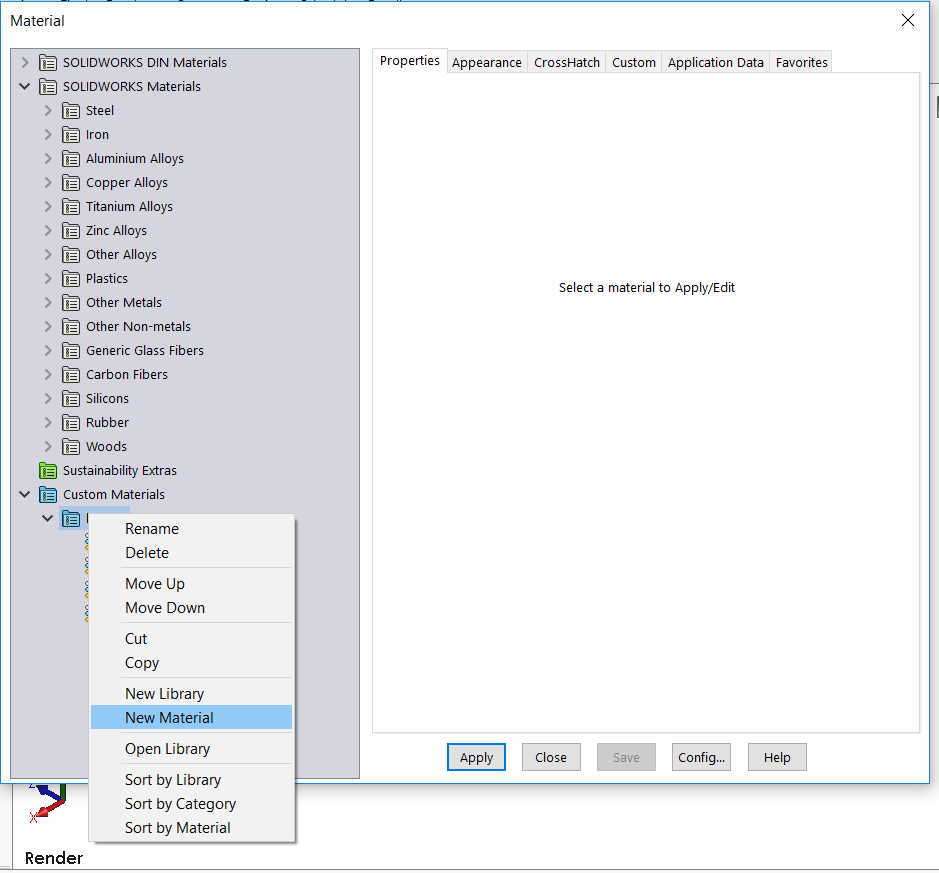
Figure 1: SOLIDWORKS Material Window with new material selected
Arm
The first objective was to test the strength of the arm. My initial concerns were the spring tearing through the material and too much-bending happening during loading.
The first simulation I set up was to test the strength of the arm when pressed against the stopper by the spring. For the boundary conditions, I wanted to fix the area where the stopper makes contact with the arm, but I did not have a selectable entity that size. This is where the split line operation comes into play. Using a sketch and the convert entities tool I can generate a face the exact size and shape of the contact area. Those steps can be seen in Figure 2.

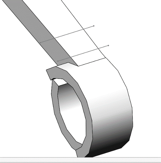
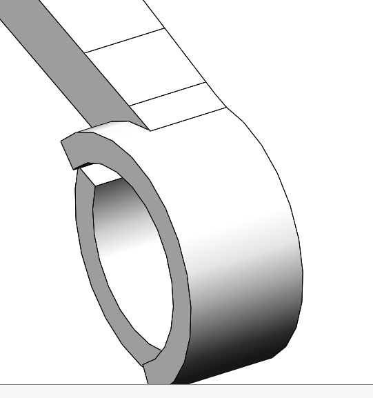
Figure 2: Method to Generate Split Face
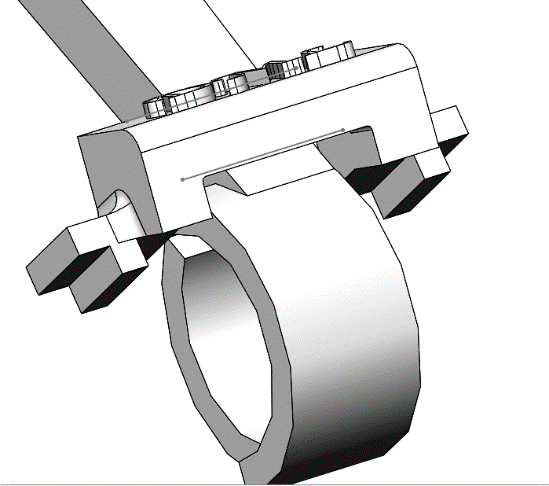
I used the fixed geometry boundary condition to remove all the degrees of freedom of the nodes on the face that will make contact with the stopper. This fixture is assuming that the stopper is infinitely stiff which will add some inaccuracy near the contact region. Since my objective is to determine the effects the spring will have on the arm and I am not concerned about the contact forces with the stopper, so this is a viable assumption to simplify the simulation and solving time. The loading of the simulation will come from the torque applied from the torsion spring. I applied the maximum output torque of the spring along the channel where it will sit as seen in Figure 3. The green color is the fixture and the purple color is the torque load.
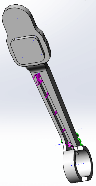
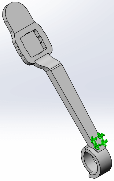
Figure 3: Boundary Conditions for Arm Strength Simulation
The validation process for this design proved very beneficial as there were some geometric features that concentrated the stress instead of distributing it. The worst culprit was the transition from round to flat where I had an abrupt direction change as seen in Figure 4. The size of the fillet was changed to find an atheistically pleasing radius that distributed the stress instead of concentrating it.
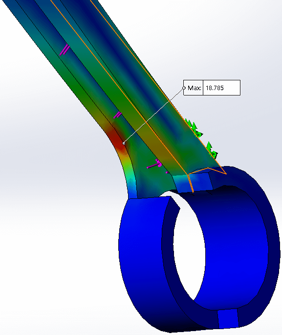
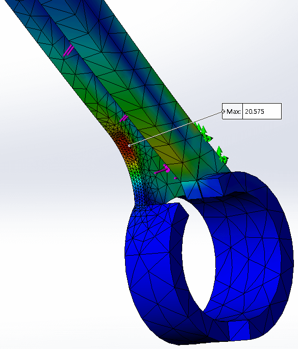
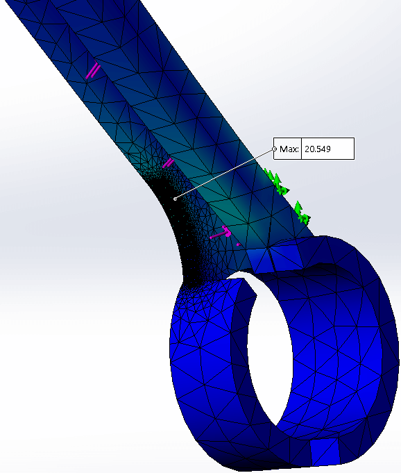
Figure 4: Location of High Stress and Mesh Refinement for Convergence
A few revisions were done to find the optimum fillet size and then a few more subsequent studies were done to prove the solution was independent of the mesh and the answer was valid based upon the boundary conditions. As you can see in Figure 4 there is no significant stress change as the mesh is refined in the area of high stress proving convergence and making me comfortable with my solution.
The final results let me conclude the design to be stable when at rest. I am comfortable ignoring the dynamic conditions because the additional carbon fiber supports added from the printing process should be more than supportive.
Stopper
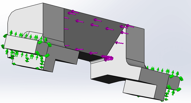
The stopper component restricts the arm from rotating, causing the projectile to launch. It is a small part and is absorbing the entire load of the catapult so I decided to study the component to validate its geometry and structural integrity. The study set up included the stopper being fixed on its connection points to the side plates of the catapult and the spring’s maximum torque evenly applied on the arms contact face. The fixtures are roller sliders, restricting the degrees of freedom normal to the connecting faces. This will artificially stiffen the design there but since I am not concerned about that portion of the design the assumption will be valid, at least for the first round of simulations. Figure 5 shows the boundary conditions used for the simulation.
The simulation revealed that the initial design was too thin and had too many sharp corners. After some fillets were added a design optimization study was generated to determine the optimal thickness for the stress to stay under 50% of yield. The optimization set up can be seen in Figure 6 where I defined an allowable range for the thickness and the design constraint.
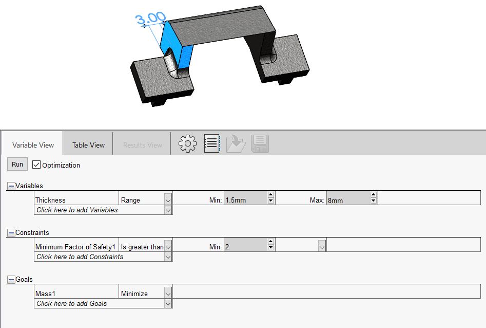
Figure 6: Optimization Design Study for Stopper
The revised design is 3 mm thicker than the original but can handle the loading of the arm now with some wiggle room for the unknown. SOLIDWORKS simulation let me virtually test and eliminate at least 3, if not more, physical prototypes. I can now start physically prototyping with some confidence in my design.
Have questions? Contact us or get started with a free trial of SOLIDWORKS Simulation.