
Whenever multiple components are to be analyzed in a SOLIDWORKS Simulation
study, contact interactions become a concern. SOLIDWORKS Simulation has some
great ways of automatically defining contact, and also to the ability to
visualize the existing contact interactions.
The Contact Visualization Plot is one method that makes it very easy to
identify the contact sets that are being used in the study and the faces they
are defined between. What actually happens behind the scenes in any of these
contact interactions is that “contact” or “gap” elements are incorporated into
the mesh at these locations.
In most practical situations it’s not necessary to be too concerned about the
contact elements behind the scenes, which is part of the reason they are not
obvious to the end user. But the contact elements are the reason you may have
noticed your mesh becomes “out of date” any contact conditions are modified.
Consider the rest of this article and companion video for more background
information or academic understanding of the contact interactions, than any
practical guidelines.
A lesser-known option within the Contact Visualize Plot to “include solver
generated contacts” allows the user to gain some insight into the actual
contact elements being placed. In the image below you can see a cylinder
separated from a plate by a gap. In this example, a bonded contact has been
manually enforced across the gap.
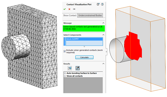 |
It’s a general recommendation not to bond across large gaps, and to treat
carefully anytime you do need to bond across a gap. In the image above we can
see some evidence of why (in this example the mesh is also fairly coarse to
exaggerate the effect) as the face of the cylinder needs to be projected onto
the plate to estimate where the contact should occur. Note: The user must
click on the “Auto Bonding Surface to Surface” result to see this effect after
calculating the solver generated contacts.
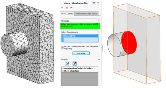
A similar recommendation is to use Split Lines to create a separate face for
situations such as this. Typically if the two components were touching, a
“compatible” or node to node mesh would automatically be enforced at their
interface which would ensure the nodes of the mesh on the plate line up with
those of the cylinder. This can be approximated somewhat manually by using a
Split Line to split the face of the plate, in the area where the cylinder
would imprint- as evidenced by the resulting solver-generated contacts with
the Split Line below.
 |
In any case, using the Contact Visualization Plot with the option for
including solver generated contacts provides the most possible information we
can extract from the software about the contact interactions that take place
behind the scenes.
For additional details on how this process can be performed, please check
out our
YouTube channel
or contact
Hawk Ridge Systems
today. Thanks for reading!


