


Figure 1: Hand sketch, SolidWorks model, real-life
A customer of ours, Jon from Weldco-Beales Manufacturing, recently came to us
with question that reminded me of my Mechanical Engineering Statics class. His
company designed a mechanism that clamped onto a tire, using a hydraulic
cylinder to provide the clamping force. He wanted to know the relationship
between the force being exerted by the hydraulic cylinder and the clamping
force exerted on the tire. Our Simulation Services Manager, Jared Conway,
presented a
Simulation webinar
using their file set and spoke about comparing the accuracy of SolidWorks
Simulation to “real-world” results. He also spoke about the need for virtual
testing because of time and monetary constraints. I’m never one for abandoning
physical testing altogether; in engineering the real-world results always win
because that is where our products are used. What I feel virtual testing can
do for us, though, is to cut down on the number of physical tests we do and
play the “what-if” game quicker and cheaper. The biggest question with virtual
testing is: how do I know my results are valid? There are several places
where, if one isn’t careful, one can get inaccurate results. The geometry,
setup, and mesh are all places you need to verify and understand any
assumptions that are made. The mesh, especially an acceptable mesh, is a
subject that’s not very straightforward. To help address this, my colleague
Damon Tordini wrote an excellent blog article on
mesh convergence
and how that can affect results.
As users, we should always question the results we get from an analysis. SolidWorks Simulation
has technical papers which look at standard NAFEMS(National Agency for Finite
Element Methods and Standards) problems and compares results, but often we
want to verify the setup and results of OUR geometry, not a hypothetical
NAFEMS problem. One way to do this is with hand calculations. For Jon, I
wanted to take our hand calculations and compare them with what SolidWorks
Simulation predicted.
In the
hand calculations[i], I assumed this to be a 2-D problem (no out of plane forces) and used
Free-Body Diagrams to keep track of the different forces and their directions.
I also assumed that all of the connections were pinned, meaning that they
allowed rotation but not translation. Knowing that we had to obey static
equilibrium, I summed up the forces and set them equal to zero. I did the same
for the moments.

When I took a step back, I saw that I had 3 equations (sum of the forces in x,
sum of the forces in y, sum of the moments around a point) to solve 3 unknowns
(force in link 1, force in link 2, and the clamping force) so I could
confidently solve this problem without needing any other information (does
anyone remember
statically indeterminate problems?).

Figure 2: The three unknowns-force in link C, force in link T, and the
clamping force F. The resolved cylinder forces are in black for reference
With this geometry, I found that with an input force from the cylinder of
99,550 lbs, the clamping force was 45,492 lbs (the ratio of input force to
output force was 2.188).
Let’s see what SolidWorks Simulation gave us. I created the geometry as a
three part assembly (the triangular clamp and the two diagonal links), using
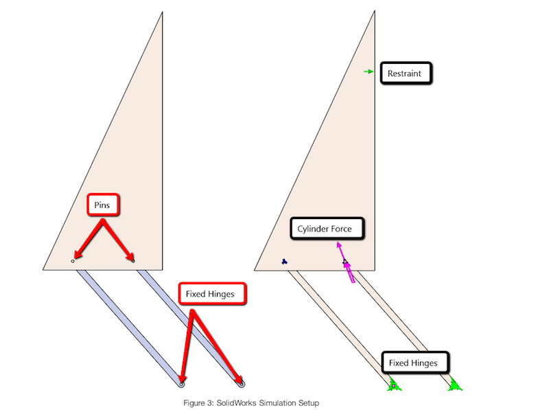
the same dimensions as in the hand calculations. I assumed fixed-hinge
constraints on the bottom pins, and pin connectors to connect the links to the
clamp. I also made sure I had a global no penetration contact set to allow for
rotation between components. I replaced the cylinder with a force of 99,550
lbs, and the tire was represented as a fixture resisting translation in the
horizontal direction.


Figure 3: SolidWorks Simulation Setup
SolidWorks predicted the clamping force to be 45,480 lbs, which was a
difference of 0.03% from the hand calculation!
As a secondary test, I tried the reverse approach. I applied my known reaction
force, 45,492 lbs, to the clamp and investigated the force being exerted on
the cylinder. In this test, I modeled the cylinder as two parallel links. I
ran the analysis and found that the reaction force along the axis of the
“cylinder” was 99,576 lbs, which again was a difference of 0.03% from the hand
calculation!

Figure 4: A reverse approach
It is always nice to know that SolidWorks Simulation has tested the validity
of the software with the NAFEMS benchmarks, but for me, to see a customer’s
problem run in Simulation and verified with hand calculations is more
rewarding.
The customer’s end goal, though, was to create a spreadsheet which showed how
the clamping force changed as the geometry of the linkage changed. Stay tuned
to see how I attempted to tackle this using SolidWorks Motion Simulation!
Customer Validation – Force Balance Appendix 1