When working with parts and assemblies, we can change display settings such as what’s hidden or shown in the graphics area, display styles, appearances, and the transparency of solid bodies or components within an assembly. There are a few ways to do this in SOLIDWORKS, but one method that I feel is underused is using the Display Pane.
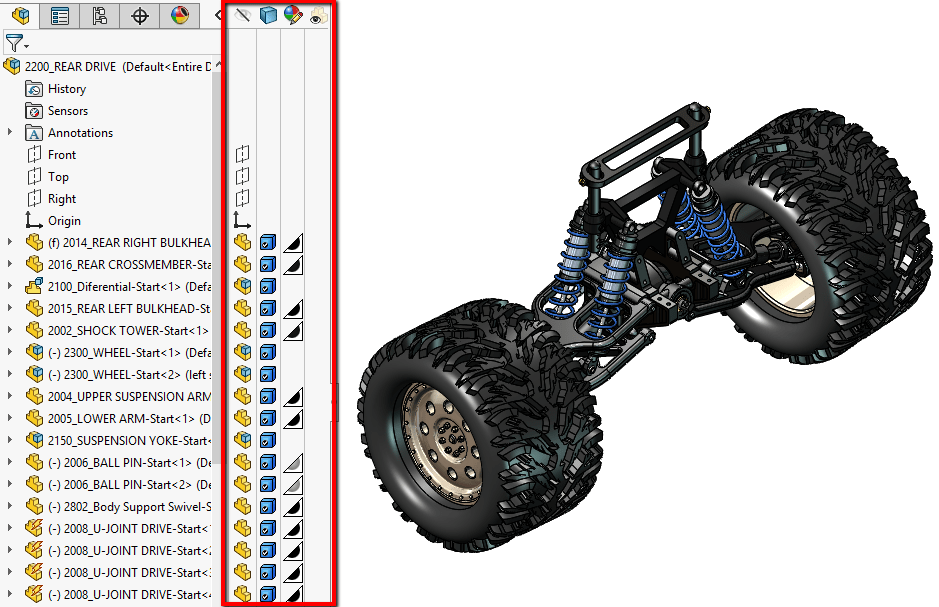
The Display Pane gives you a quick visual reference to view the display settings mentioned above, and also allows changes to be made very quickly. It is located at the top of the FeatureManager Design Tree and can be expanded/collapsed by clicking on the arrow.

When expanded, you’ll see that the Display Pane is divided into columns, with icons on the top indicating Hide/Show, Display Style, Appearance, and Transparency. Each of these can be changed for items in the FeatureManager Design Tree such as planes, sketch entities, solid bodies, components, etc, by clicking in the appropriate column next to the tree item.
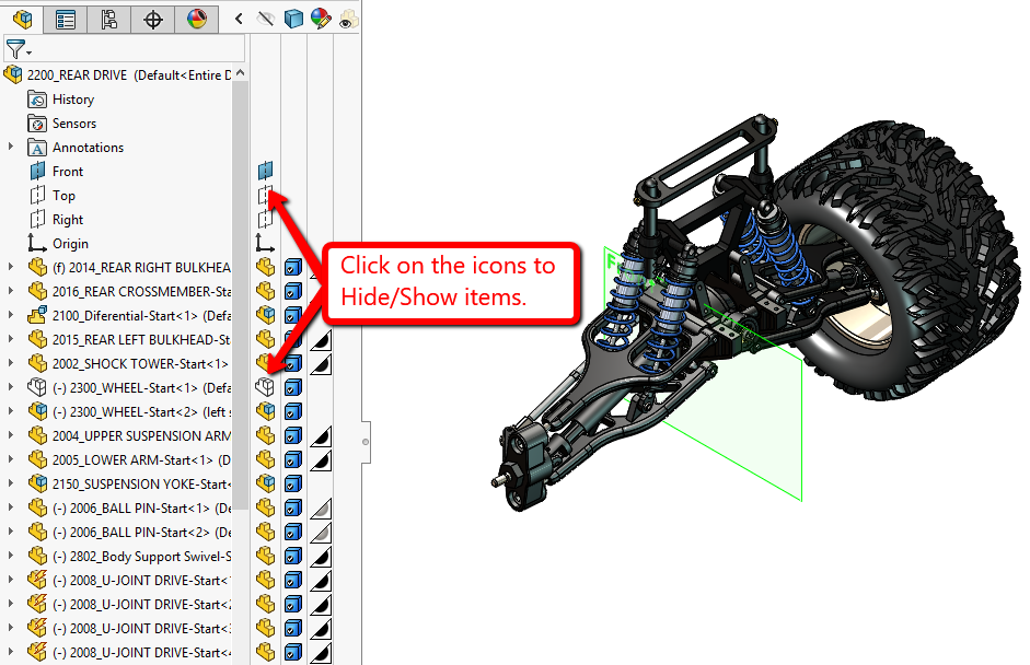
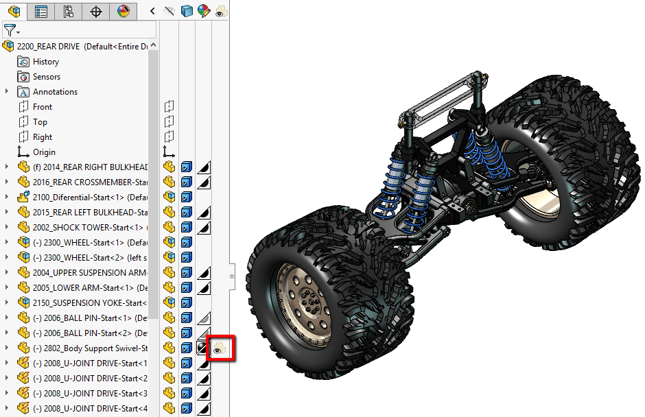
The first column, Hide/Show, allows users to see what is shown or hidden based on the icon next to the feature or component in the tree. Items that are shown in the model will have a shaded/colored icon in the Display Pane column. You can click on these icons to toggle the items (such as planes, sketches, components, etc) to be hidden or shown.
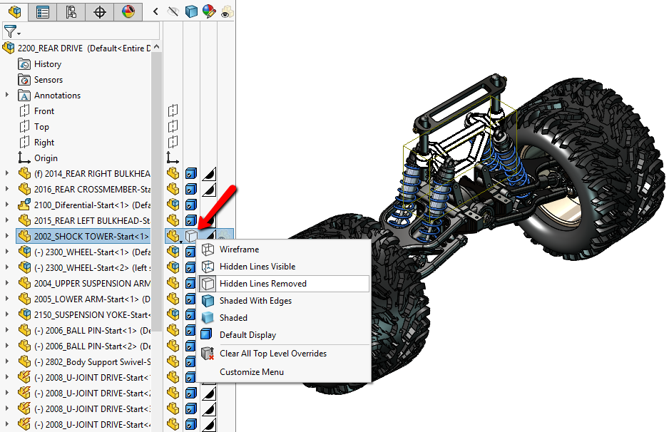
The second column controls the Display Style. By default, the display style for components in an assembly or bodies in a multibody part will be set to the default style that’s set in the Heads-Up toolbar. The display style for specific components or bodies can be set by clicking on the icon in the Display Pane as well.
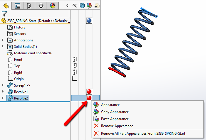
The third column is for Appearance. In the part environment, the icon in the Appearance column next to the file name at the top of the FeatureManager Design Tree displays the color applied to the part. If any appearances were applied to specific features, it would show next to the feature name. You can click on these icons to access different options to apply, copy, paste, or remove appearances. (Note that the icon will only appear next to features once an appearance has been applied. However, you can still click in the area where the icon would be to access the same options.)
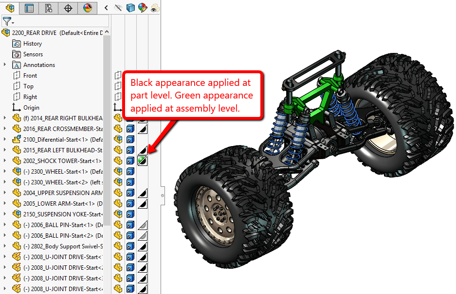
In the assembly environment, the appearance icon is split in half, diagonally. The bottom half of the icon will display appearances that were applied at the part level. Appearances that were applied to the component at the assembly level will be shown in the top half. The same appearance options can be accessed by clicking on the icon in the column.
The final column is Transparency. The transparency column won’t have an icon showing unless the component is made transparent. However, the transparency of a component can still be toggled by clicking in the transparency column next to the component.
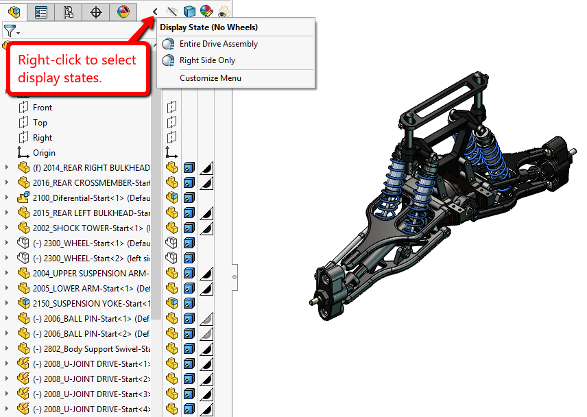
Additionally, if there are any display states created in the model, you can switch between them by right-clicking on the arrow that expands/collapses the Display Pane. This will pop-up a menu with the different display states, and you can you can click on one to switch it.
I use the Display Pane a lot when working in SOLIDWORKS and I hope that you all find it useful as well. For more information, check out our YouTube channel, get a SOLIDWORKS 3D CAD quote or contact us at Hawk Ridge Systems today. Thanks for reading!


