For customers of Hawk Ridge Systems, one of the most popular uses of SOLIDWORKS Flow Simulation has long been predicting the performance of hardware and industrial equipment – things like valves, manifolds, and piping systems. Engineers commonly use Flow Simulation while designing such components to ensure a certain fluid delivery rate, minimize pressure resistance and select the right pumping equipment- even including certain processes like heat transfer or mixing of fluids.
In mixing problems, such as exhaust gas recirculation or blending liquids, it’s always been possible to see mass or volume concentrations, density changes and more- even with as many as ten different fluids- but there was always one major caveat. Until now, it has only been possible to mix fluids of the same phases (gasses with gasses, liquids with liquids), which mean it was impossible to simulate any system with a free-flowing liquid surrounded by a gas- for example, water sloshing in a tank, or aeration in a static gas-liquid mixer.
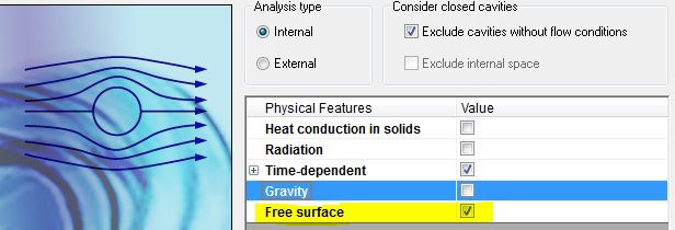
All that has changed with SOLIDWORKS 2018, with Flow Simulation’s new “Free Surface” capability. When creating a new project, you’ll be able to select this option at the Analysis Type menu. When proceeding to the Fluids tab and selecting both a gas and liquid, such as air and water, the Default fluid type will now show as “Immiscible mixture” – meaning they can now occupy the same volume.
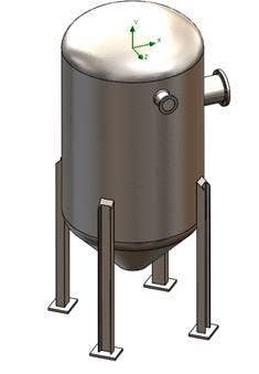
I’m using this new capability to perform a tank filling simulation so I can confirm the tank will fill as quickly as I want, and get an idea of how powerful my pump needs to be.
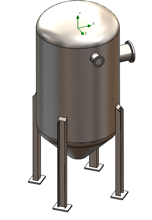
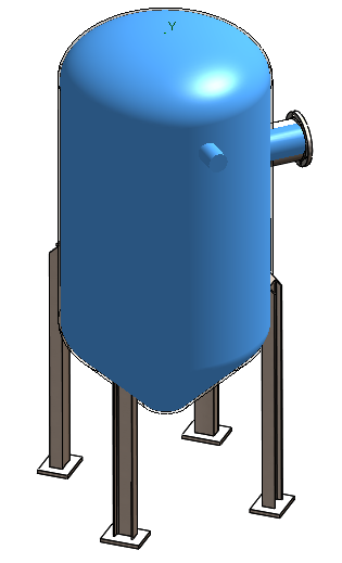
Once you’ve enabled the option, you’ll then be able to select which fluid- the air or gas- is present at the start of the analysis (using the Free Surface capability requires a transient analysis). Similarly, each Boundary Condition will let you choose which fluid will enter the system at that opening. In this case, I’m starting the simulation with a tank full of air, and then applying a Volume Flow Rate of 500 gal/min of water to the inlet pipe:


After running the project (which, like other transient studies can be sped up with the Nested Iterations option), I can review all the normal plots types and Goals with such parameters as pressure, velocity, and mass or volume fractions- and using the Transient Explorer capability with a Cut Plot can provide an insightful transient animation of the filling process:
This technique does have a few limitations- being a VOF (Volume of Fluid) method, there’s no accounting for surface tension effects on the shape of the liquid surface, so visualizing individual droplets or bubbles isn’t possible. Also, porous materials and rotation are not supported in this release.
However, enabling Free Surface doesn’t add much to solve times, and is more than capable for predicting pressure buildup, fill rates, turbulence, and any other large-scale effects. In this case, it looks like my tank will be half full after 30 seconds, and since the pressure increases as the water builds up, I’ll need a pump that can provide at least a couple PSIg to do the job.

Stay tuned to the Hawk Ridge Systems blog for more examples of analysis in action, and all the new capabilities in SOLIDWORKS 2018. For more information, check out our YouTube channel, get a SOLIDWORKS Flow Simulation quote or contact us at Hawk Ridge Systems today. Thanks for reading!
