In Part I of this series, we looked at how the smoothness of curves can be analyzed and controlled. Now we’ll be taking a look at some additional analyses tools to further evaluate our surfaces as well as ways to improve our curvature continuous connections.
The zebra stripes tool (view>display>zebra stripes) allows us to see small changes on a surface that may be hard to see with a standard display. This tool mimics the reflection of long stripes of light on a very shiny surface. With zebra stripes, we can verify that two adjacent faces are in contact, are tangent, or have continuous curvature. As can be seen in the image below, the zebra stripes for contact do not have the same direction or size. The zebra stripes for tangent have the same direction, but change sizes where the tangency occurs – there are two points of tangency. And the curvature continuous stripes share the same direction and the same size throughout the entire surface.

We can even use our curvature display tool to further analyze our surface. The curvature display tool (view>display>curvature) displays the local radius of curvature in different colors based off of the curvature value. Surfaces with the least amount of curvature are displayed in black and the colors change through blue, green, and red as the curvature values increase (red indicating surfaces with the most curvature).


There are different ways to optimize curvature continuous connections between splines. One way is by using the equal curvature sketch relationship. This matches the radius of curvature and the direction between two splines, ultimately creating a smoother transition between the two entities.


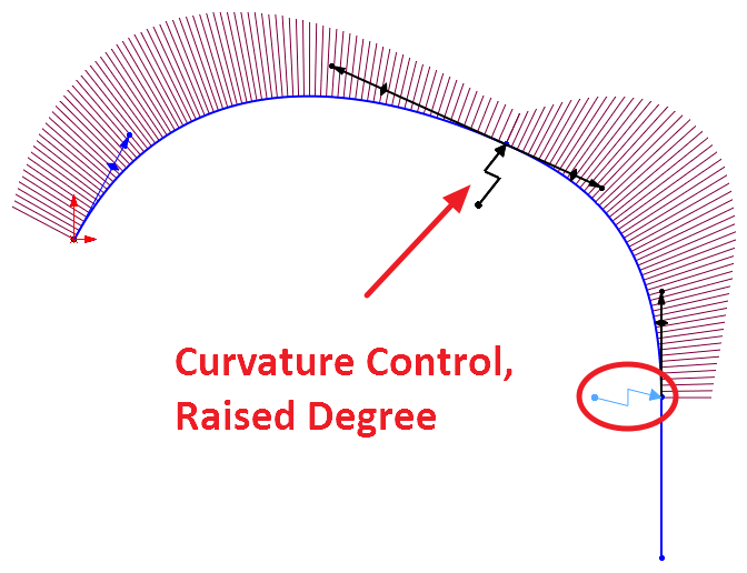
Another way to create a smoother transition between entities is by using the curvature control tool (right click a spline>add curvature control). The curvature control tool allows us to control the radius of curvature at a certain point on our spline. More importantly, it allows us to select an additional option which enables us to have a smoother transition between the entities. This option is called raised degree and is available in the property manager of the curvature control tool after it is placed on the spline. By selecting the raised degree option, SOLIDWORKS mathematically makes the spline smoother by adding additional control points. This option is automatically applied to splines that have equal curvature relations on both ends of the spline. As seen in the image below, the curvature combs have a smoother transition when the raised degree option is enabled versus not.


By utilizing all of these tools we can ensure that our surfaces will be as smooth as possible. If you want additional information on splines, specifically style splines, read the following articles: The Style Spline in SOLIDWORKS – Part 1, The Style Spline in SOLIDWORKS – Part 2 & The Style Spline in SOLIDWORKS – Part 3.
For more information, request a SOLIDWORKS 3D CAD quote or contact us at Hawk Ridge Systems today. Thanks for reading!


