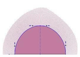
I like nice curves and I cannot lie. And in SOLIDWORKS we can control exactly how smooth our curves are. When it comes to curves in SOLIDWORKS, there is a difference between what is smooth and what looks smooth. This blog will discuss how we can analyze our curves and control how smooth they really are by using surface evaluation tools and different spline tools.
The quality of a great surface lies within the curve that defines it. These curves are ideally created and controlled through splines. The spline sketch tool creates a smooth curve through the position of control vertices, or CV’s. Controlling the quality of our splines will ultimately control the quality of our surfaces. Splines can be analyzed using the curvature combs tool. The curvature combs tool graphically shows the amount of curvature at a given point on a sketch element. A smooth curvature comb is desired to produce the smoothest surface. As shown below, both splines look the same until we look at their curvature combs. The spline with the smoothest curvature combs (i.e. no flat spots or dips exist) will produce the smoothest surface.
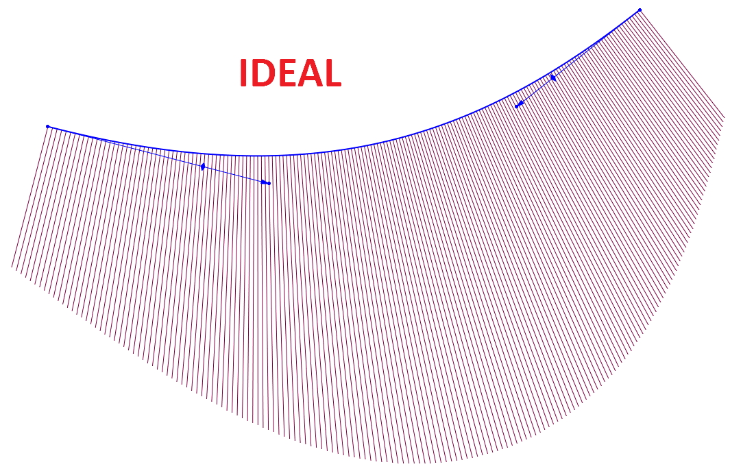
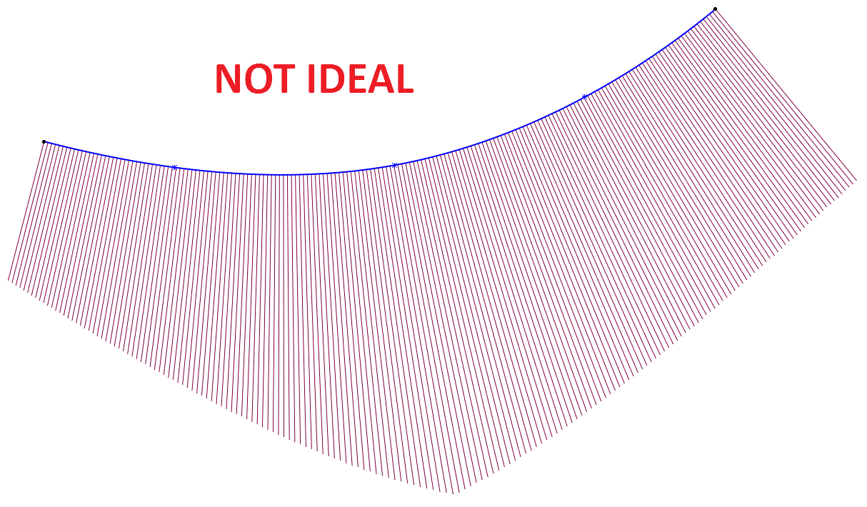
To create smooth curvature combs, splines should be created with the least amount of points possible. Just as seen above, both of these splines are identical. The difference in curvature combs is due to the fact that the spline on the left was made with just 2 points, whereas the spline on the right was made with 5.
If multiple points are required, then the spline should be modified by using the control polygon tool as opposed to the spline handles. This can be activated by right clicking on your spline and clicking on Display Control Polygon. The control polygon will allow the spline to be manipulated while keeping the curvature combs as smooth as possible.
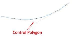
An even better method for creating a spline with multiple points is by using the style spline tool. This spline tool creates a spline by drawing its control polygon and using that control polygon to control the shape of the spline. This allows for smoother curvature combs since we’re using the control polygon instead of the spline handles. As stated above, controlling a spline through its control polygon allows for smoother control of the curvature combs which ultimately will create a smooth surface.
Curvature can be mathematically defined as the inverse of the radius (i.e. k=1/r where k is the curvature). There are three different degrees of curvature that we are concerned with in SOLIDWORKS. Curvature is defined as the The first degree is called contact (or C0 continuity) and is when two entities meet. These entities will ultimately create an edge, so there is no smoothness on the surface created by them. At the sketch level, this means the curvature combs will not touch or have a smooth transition between each other.
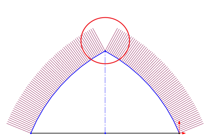
The second degree is called tangent (or C1 continuity) and is when two entities touch, and the angle of both curves are equal. This would be a situation where a tangent sketch relationship is created between two entities. Although this provides a smooth surface, the transition would be noticeable as seen in the image below. This situation would be acceptable for most applications, but is not aesthetically pleasing.
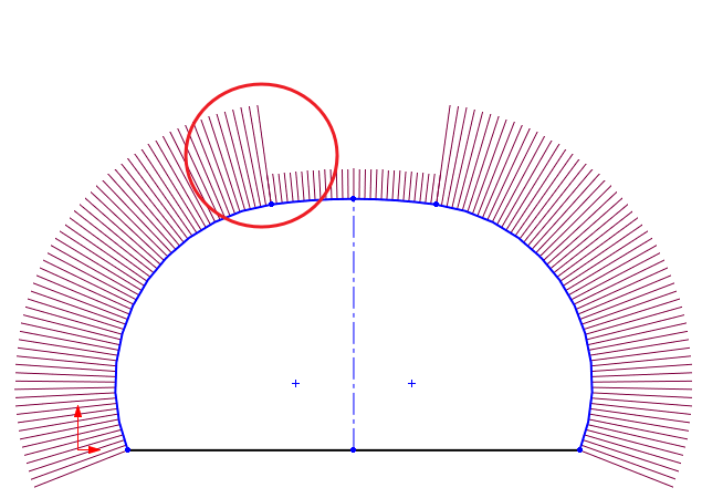
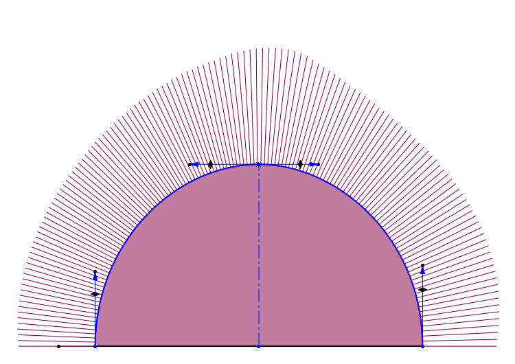
The third degree is called curvature continuous (or C2 continuity) which is when the two entities have the same curvature amongst each other. The radius of their curvature combs is equal as well as their angle. This type of curvature would provide the smoothest type of surface in SOLIDWORKS.
Part 2 of this series will further discuss how to further analyze surfaces and can be found. For more information, check out our YouTube channel, get a SOLIDWORKS 3D CAD quote or contact us at Hawk Ridge Systems today. Thanks for reading!
