Fall is always a great time of year. Football is in full swing, the World
Series is around the corner, there will be snow in the mountains soon, and, of
course, new features in SOLIDWORKS Simulation are unveiled.
This year,
SOLIDWORKS 2015
has a new tool called Shell Manager which will drastically reduce the time it
takes to define shells and simplify the modification of them in your next
simulation.
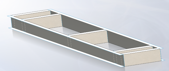
Shells are ideal for the analysis of high aspect ratio parts such as sheet
metal or components with one dimension, the thickness, significant smaller
than the other two. It seems like just yesterday that SOLIDWORKS 2013 provided
the ability to Render Shell Thickness in 3D, improving the visualization of
results during post-processing. Earlier this year ilyn our blog
Render Shell Thickness in SOLIDWORKS Simulation, we discussed this enhancement as well as some basics of using shell
elements in an analysis, a nice resource to review if needed. If you have
already been using shells, or perhaps found them too tedious to setup in an
analysis you will want to read on to learn more about the Shell Manager.
I will be using the Shell Manager anytime I have more than a couple of shells
in an analysis. The on-screen feedback and single location to control many
properties of my shell definition is a welcome change from having to select
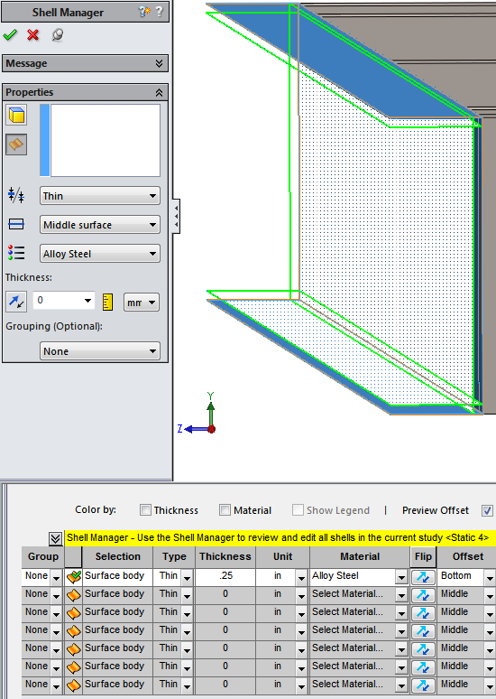
each shell individually if changes are required. Now, I only have to right
click on a body or previously defined shell in the Simulation Tree and choose
to access the Shell Manager tool. I can enter and/or modify the definition
using the property manager or I can input parameters in tabular form at the
bottom of the screen. All of the same shell definitions are available through
the new tool such as type, thickness, and offset, but now I can also easily
define the material in the same interface.
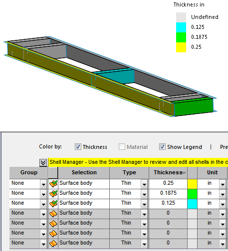
As I create more and more shells in my model, I can always check to ensure my
definitions are accurate using the Shell Manager. The Preview Offset allows me
to verify that the shells accurately represent my 3D model, while the “Color
by:” choices of “Thickness” and “Material” allow for on-screen visual feedback
to show which material is used on which shells or if all of my cross-member
shells are the proper thickness.
The increased feedback and input options are great during shell definition,
but the real time-saver is when I have design changes that I want to quickly
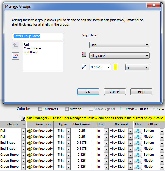
implement in my analysis. I can now group shells with the same definition
together using Shell Groups. This provides one location where I can change the
type, material, and thickness of multiple shells with one dialogue box instead
of modifying each individual shell. In my example, I have 3 Shell Groups to
modify instead of the 7 individual shells – imagine the time-savings if I had
30 shells in my model that are now in just 3 Shell Groups. An awesome
efficiency improvement for SOLIDWORKS Simulation 2015. Bring on the design
changes, I am ready!
I’ll be showing new features like this at our SOLIDWORKS 2015 Launch events in
Las Vegas, Reno, Northern California,
Southern California, Portland, and Seattle in just a few weeks. Join me and the rest of Team Hawk Ridge for the Launch
event, which includes a networking hour with drinks, food, and prizes. My
counterparts in Canada will visit
Winnipeg, Toronto, Vancouver, Saskatoon, Calgary, and Edmonton. Click on the location nearest you for more details.
Also, please keep an eye on our YouTube channel for an upcoming video demonstrating this new tool and other enhancements for
SOLIDWORKS 2015 as well as great tips and tricks for all of the SOLIDWORKS
Products.