

Drag forces due to air resistance are a key design factor for vehicles on the ground and in the sky. Current trends toward electrification have put even further emphasis on minimizing drag as a means to extend range or increase flight time when all other things are equal. This is relevant both for the designers of airframes and chassis, as well as suppliers of exterior-mounted third party equipment.
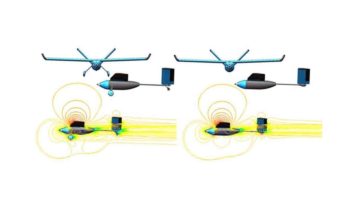
Performing predictions of lift and drag is a very straightforward process in SOLIDWORKS Flow Simulation and can be performed early on during design. This reduces the need for iterations of scale prototypes and wind tunnel tests and provides additional confidence in a design before committing to prototyping. Design variations can be quickly analyzed by cloning Flow Simulation projects between multiple SOLIDWORKS configurations.
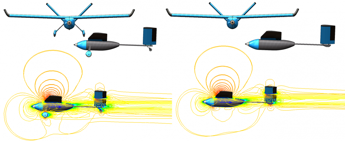
Evaluating competing designs in SOLIDWORKS Flow Simulation
Flight envelope characteristics can also be predicted by either or both of the following approaches:
- Utilizing parametric studies to vary flow conditions or the orientation of geometry to perform studies iteratively
- Varying flow conditions dynamically using dependencies inside a single transient analysis.
Parametric studies also allow rapid and automated iteration of potential design changes with the ability to link to SOLIDWORKS model dimensions and vary them over ranges.
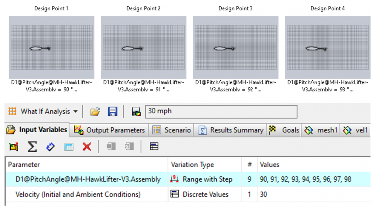
Parametric Study batch iteration and optimization
Creating a refined mesh in SOLIDWORKS Flow Simulation is easy, taking advantage of various tools such as defining a level of refinement at the solid/fluid interface, utilizing equidistant local mesh to create “shells” of refinement around the object, or taking advantage of solution-adaptive meshing.
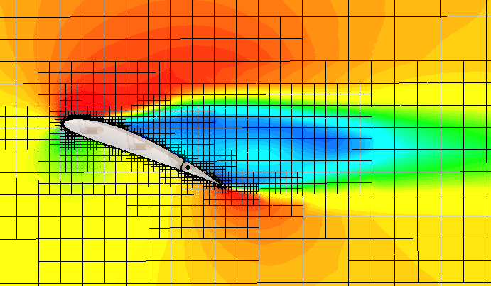
Solution-adaptive mesh in Flow Simulation used in a stall condition
For problems that require analysis of detailed turbulence as the result of wakes or vortex shedding, SIMULIA xFlow offers several advantages. Its Lattice-Boltzmann solver and highly dynamic adaptive refinement are able to capture turbulence in incredible detail.
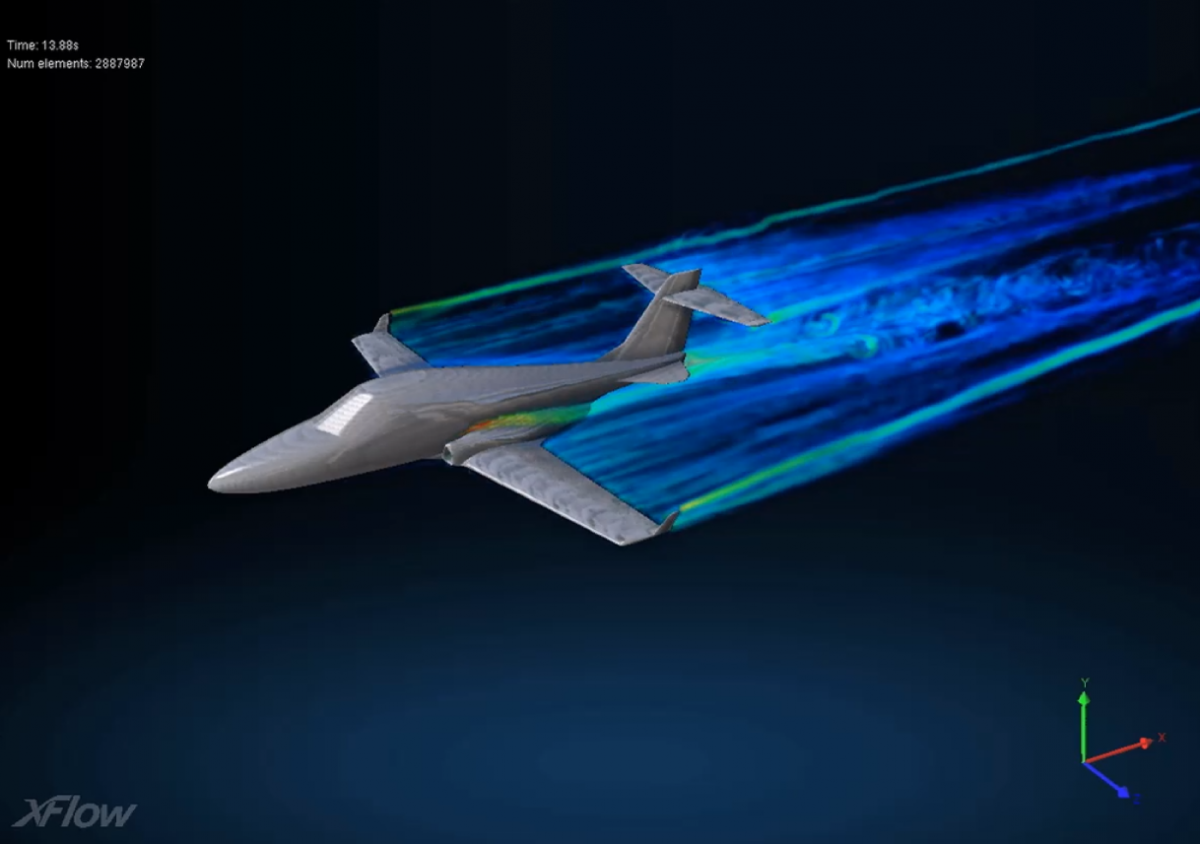
SIMULIA xFlow also features native support for body motion (both actively forced and reactive to the fluid flow) which allows for performing virtual flight or vehicle maneuvers and stability analysis – a longstanding limitation of SOLIDWORKS Flow Simulation and most “conventional” CFD packages.
See It In Action
Watch our recent webinar to see how these techniques and setup processes are discussed in-depth.
For more information on how SOLIDWORKS Simulation tools can fit your application, don’t hesitate to contact us at Hawk Ridge Systems today. Thanks for reading!
Put your next design into motion
Explore solutions and expert guidance for your application.
Ask an Engineer
Written by Ryan Navarro
Ryan Navarro is a mechanical engineer and an avid SOLIDWORKS user since 2007. As product manager for CFD analysis, he specializes in complex simulations related to fluid flow, as well as structural interactions and mold filling.