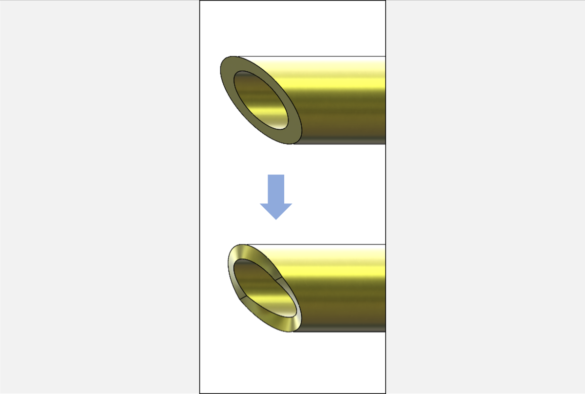
Looking for a tutorial on normalizing coped tube cuts for manufacture? You’ve come to the right place. Modeling a mitered tube cut is done with the click of a button in SOLIDWORKS Weldments, but preparing the geometry for laser cutting or similar processes can be involved. We’ll run through a few methods on how to represent these manufacturing processes in SOLIDWORKS.
To see how to normalize coped cuts, check out our SOLIDWORKS Coped Cuts how-to article.
Using the Standard Method for Normalizing Mitered Tube Cuts on SOLIDWORKS Weldments
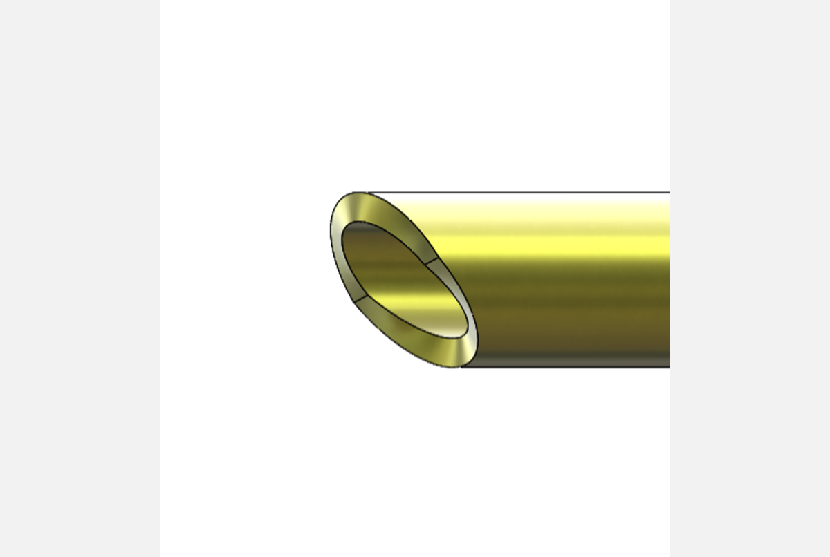
The ideal way to create a normalized end cut is trimming the outer tube surface and offsetting it inward using the Thicken command. This extrudes the outer surface normal to the tube axis. If the outer tube surface is not an acceptable reference, examine the other methods in this article. This method should work for a mitered cut at one end and a straight cut on the other, or for a mitered cut on either end if the steps are applied to both ends.
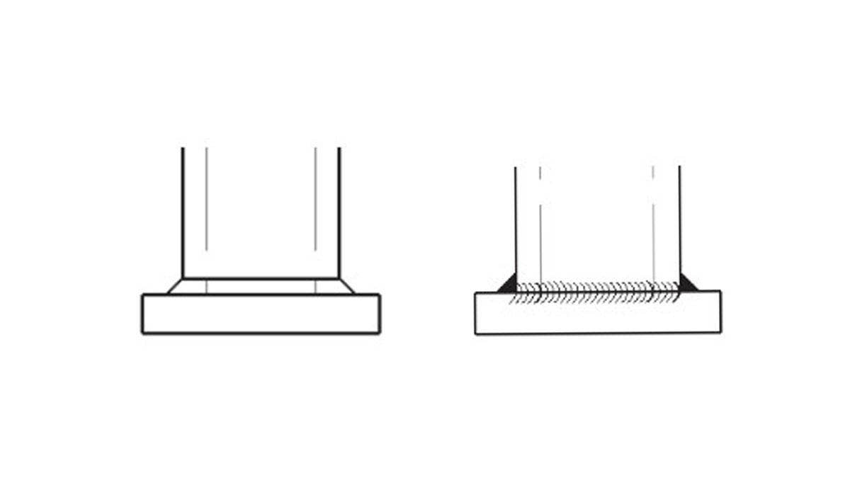
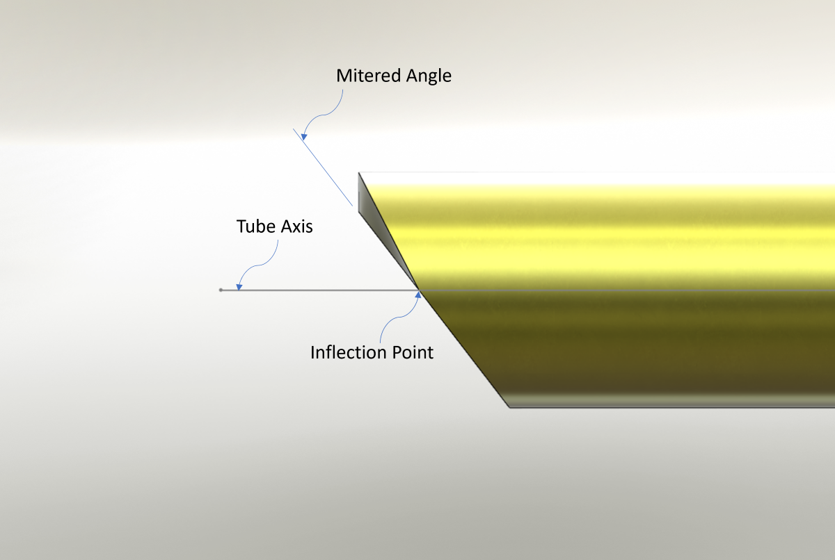
Because of the inflection point (as pictured above – for more information see the end of this article), half of the end face must reference the inner surface while the other half must reference the outer.
Step 1 – Create a Ruled Surface
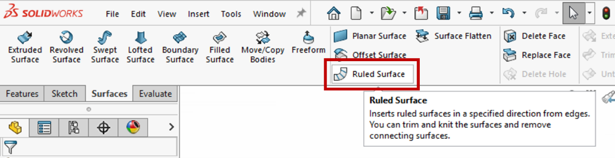
We’ll begin with the inner surface. First, isolate the tube and launch the Ruled Surface command from the Surfaces tab of the CommandManager.
In the PropertyManager, select “Normal to Surface” for Type, then activate the Edge Selection box (pink). Locate the cuts that need to be normalized and select their inner edge. This will create a surface that is normal to the tube axis and coincident with the inner edge. Lastly, ensure the Distance/Direction exceeds the outer wall of the tube. Both checkboxes in the Options field should be cleared. Click OK to accept and create the surface.
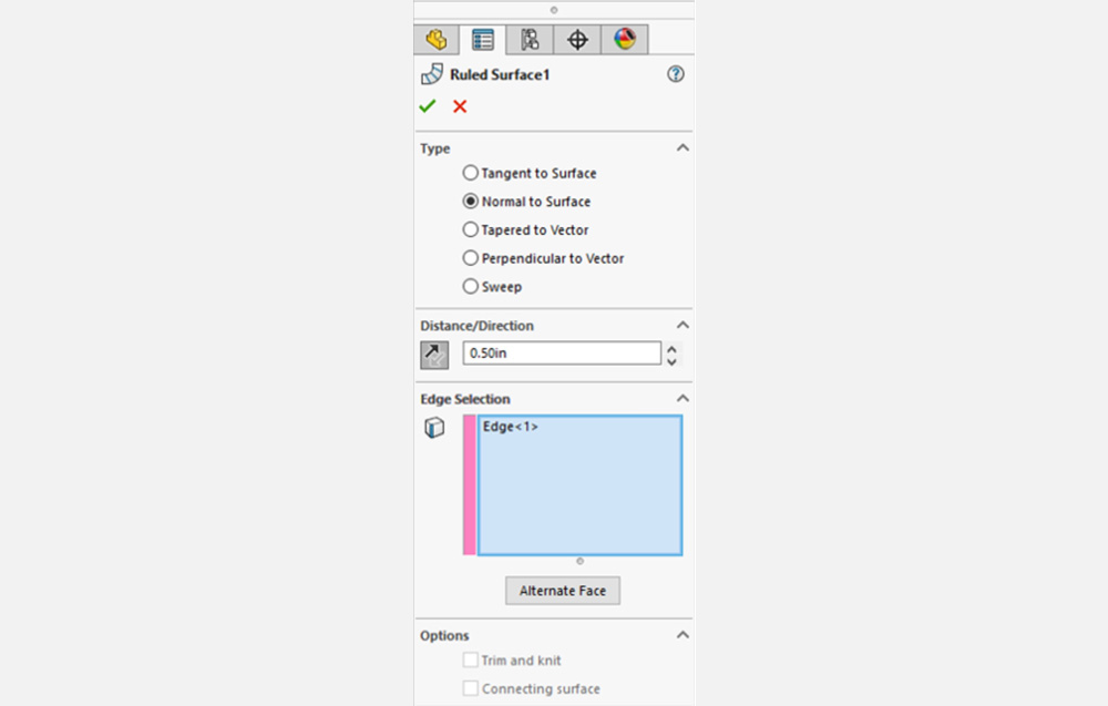
A ruled surface can be thought of as sweeping a line segment around a given path. When we select the “Normal to Surface” option, we are constraining the ‘line’ to be perpendicular to the axis of the tube. For this reason, the same result can also be achieved by selecting the “Perpendicular to Vector” option and choosing the tube axis as the vector.
Step 2 – Delete Faces
Next, activate the Delete Face command from the Surfaces tab of the CommandManager.
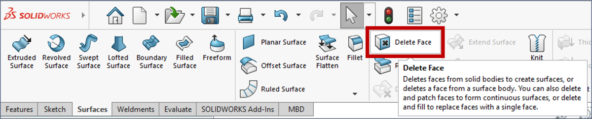
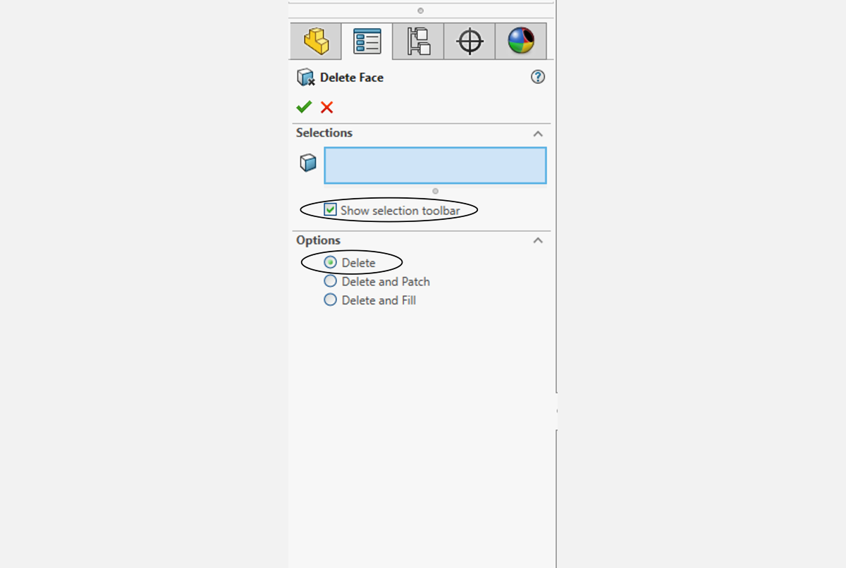
In the Delete Face PropertyManager, ensure the “Show Selection Toolbar” option is checked and Options is set to “Delete”.
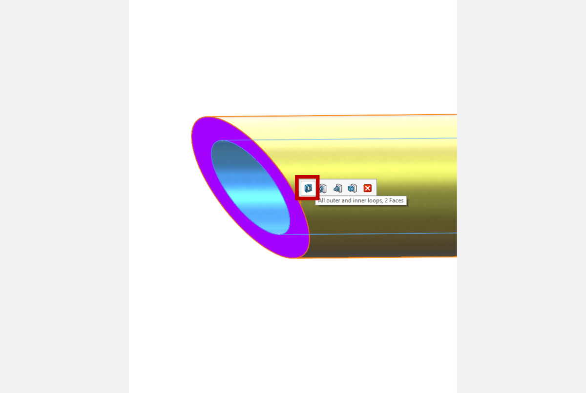
Select the INNER tube surface and do not move the mouse. A context-sensitive window pops up giving quick shortcuts for group selection. Choose the “All outer and inner loops” group selection.
Important: this should highlight ALL surfaces on the tube except the outer surface and ruled surface. If it does not, toggle the selection options or manually select the surfaces to complete this step.
Delete these surfaces by clicking OK. Again, check that only the outer surface and ruled surface remain.
Step 3 – Trim the Outer Surface
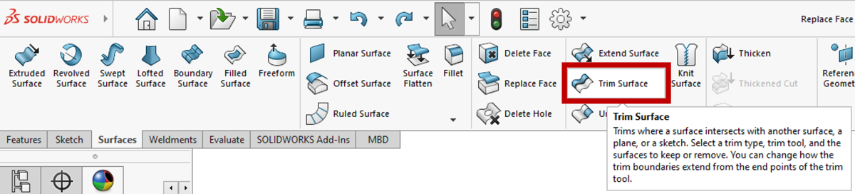
Activate the Trim Surface command from the Surfaces tab of the CommandManager.
In the PropertyManager, select “Standard” for Trim Type, then activate the Trim Tool selection box and choose the ruled surface as the Trimming Surface. Toggle to the “Keep Selections” option and click the main body of the outer surface.
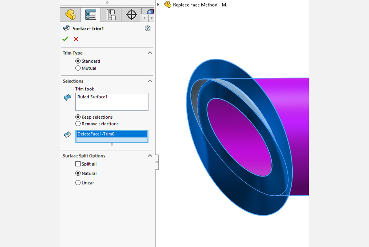
Trim the surface by clicking OK. This should create a small inflection on the end of the tube surface. The ruled surface can be removed using the Delete/Keep Body command.
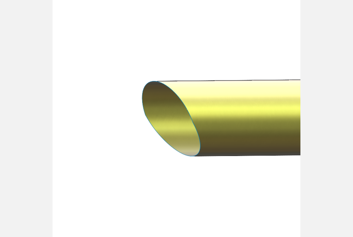
Step 4 – Thicken Surface
Lastly, select the outer surface body and use the Thicken command to extrude to the desired wall thickness. Merge result does not need to be checked.
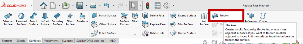
The Thicken command works by creating a normal offset surface and closing the volume with normalized end faces, so in effect the cut has been normalized!
Using Alternative Methods for Normalizing Mitered Tube Cuts on SOLIDWORKS Weldments
If deleting faces is out of the question for whatever reason, then we can employ another method to cut back the end of the tube to reference surfaces. This can be done with the powerful Replace Face command.
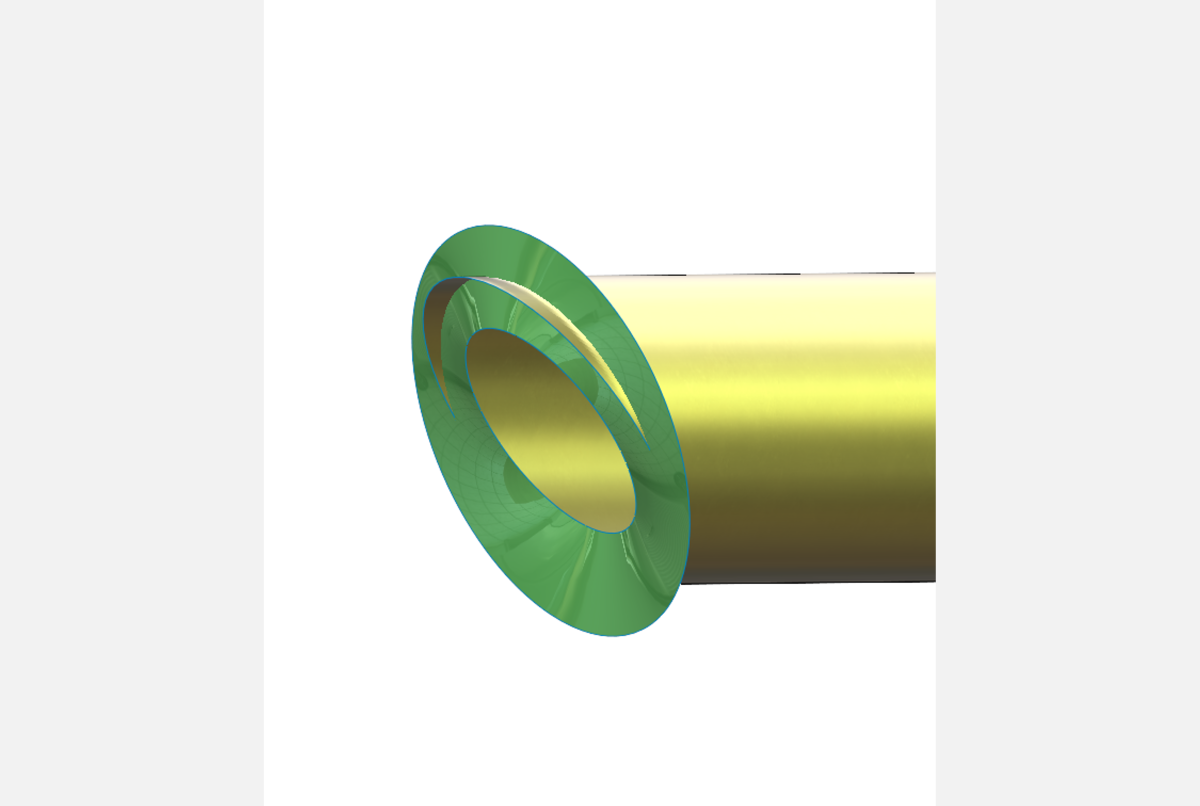
Step 1 – Create Ruled Surfaces
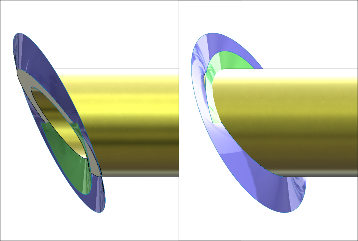
The first step in this method is the same as Step 1 in the Standard Method, so review those steps and return here. After that, a second ruled surface must be made in the same fashion but this time referencing the OUTER surface edge in the Edge Selection box. The result should look like the picture below.
Step 2 – Create Split Line
In the Standard Method, the inflection point is made by trimming the outer surface to a reference surface. The nature of this second method requires that we create this inflection point first before modifying the end face. We’ll do this using a Split Line.
Activate the Split Line command.

In the Property Manager, the Type of Split is “Intersection”, the Splitting Surface (pink) is the ruled surface coming from the INNER edge, and the Face to Split (blue) is the end face. The image below shows only the relevant ruled surface for clarity.
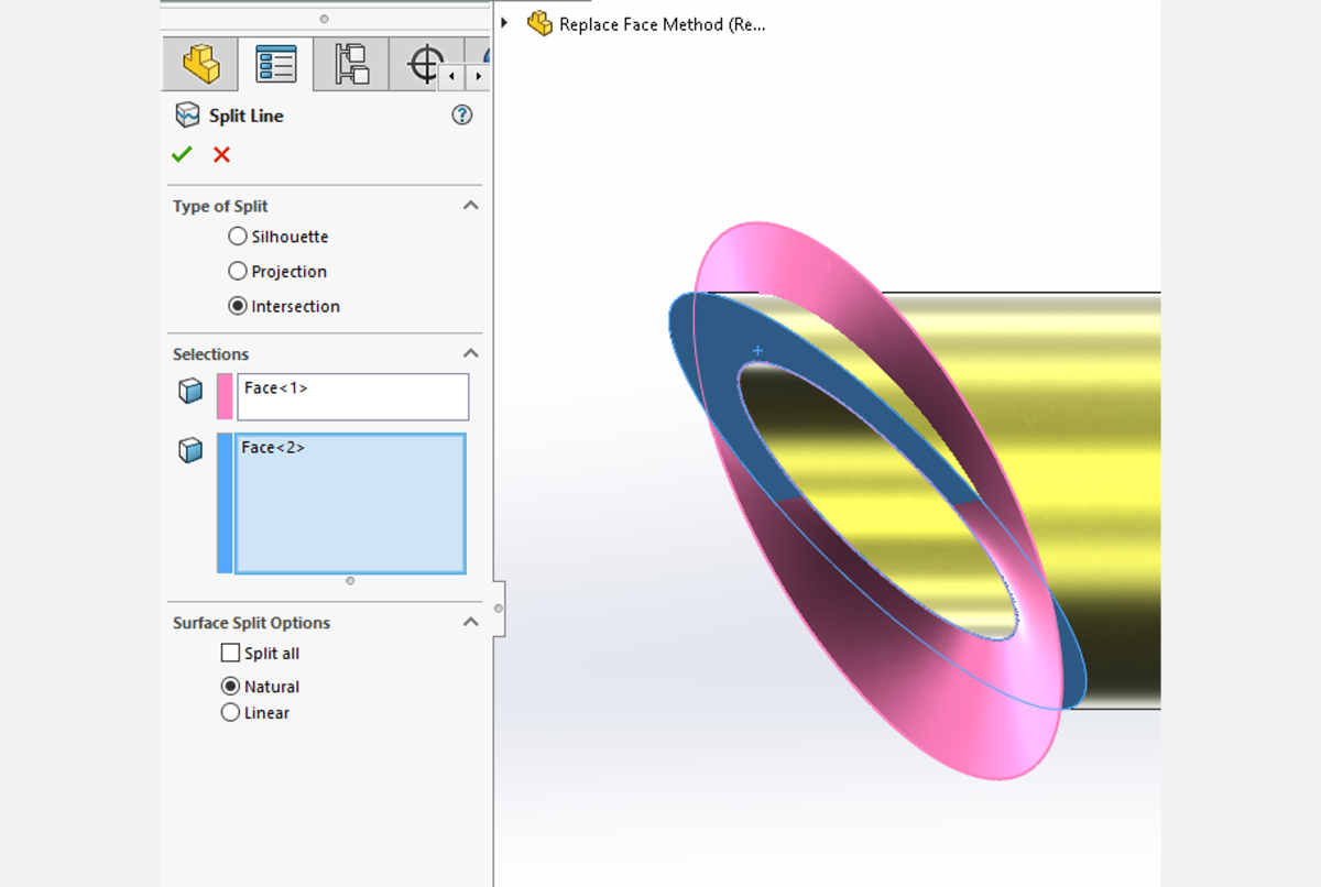
Click OK to accept, and verify that the end of the tube has been split into two faces.
Step 3 – Replace Face
The Replace Face makes light work of modifying the end of the tube, but it requires an additional ruled surface, so be sure to follow these steps carefully.
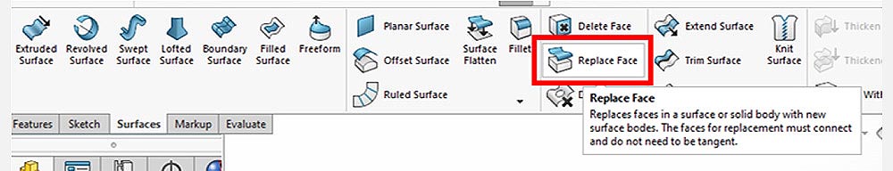
Begin by activating the Replace Face command from the Surfaces tab of the CommandManager.
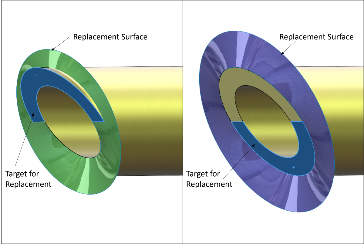
In the PropertyManager, select the ‘upper’ half of the tube face as the “Target for replacement” and select the ruled surface touching the INNER edge as the “Replacement surface”, as shown below. Click OK to replace this half of the end face.
Repeat the command making the opposite selections – the ‘lower’ half of the end face, and the ruled surface touching the OUTER edge – and click OK to replace.
Time-saving tip: This can be done in one Replace Face command, so long as the order in which the Target Faces are chosen matches the order in which the Replacement Surfaces are chosen.
Now the surface bodies can be removed using Delete/Keep Body, and the cut has been normalized!
Additional Information
If you are familiar with normalizing coped cuts, you’ll find that this process requires some extra steps. This is due to an inflection point that occurs where the leading surface of the mitered cut switches from the inner surface of the tube to the outside. This complicates the normalization process because half of the end face must reference the inner surface while the other half must reference the outer, so two separate modifications must be made.
If the Replace Face method does not work, then a more robust method using Cut with Surface can be employed. Watch our short video on how to create a coped cut perpendicular to a pipe and make sure to watch until the end for tons of troubleshooting tips.
Get More Training for SOLIDWORKS Modeling and Weldments
Want to know more? Get world-class training from our highly qualified live instructors. We offer a variety of courses including:
SOLIDWORKS – Surface Modeling Course
If you have other questions or needs for engineering services, please contact our team and visit us at hawkridgesys.com.


