When I mention the word “multibody”, I hope it doesn’t bring up the bowling
dream sequence in The Big Lebowski because that’s an out-of-body experience. A
multibody part is a part in SOLIDWORKS that is made up of multiple solids
and/or surfaces within the same part file. These bodies can be touching or not
touching, but if they aren’t touching, then they are separate bodies by
default. You can make multibody parts using various modules within SOLIDWORKS,
but this article will focus on creating multibody sheet metal parts within the
sheet metal module.
Making a multibody sheet metal part is easy and useful. Some reasons you would
make this type of part is if you are working with different gauges and
different materials of sheet metal within the same part. Also, if the bodies
are within the same part, if you change a dimension or relation of one part,
everything will change accordingly. This insures that your parts fit together
when you are done with your design.
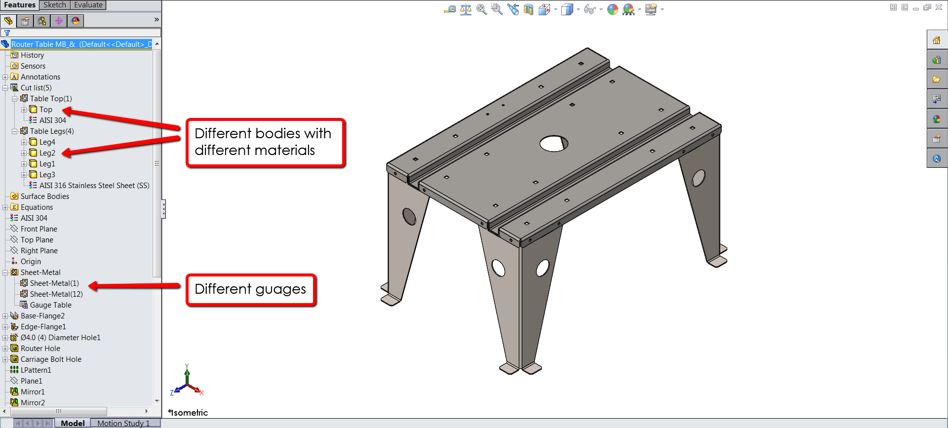
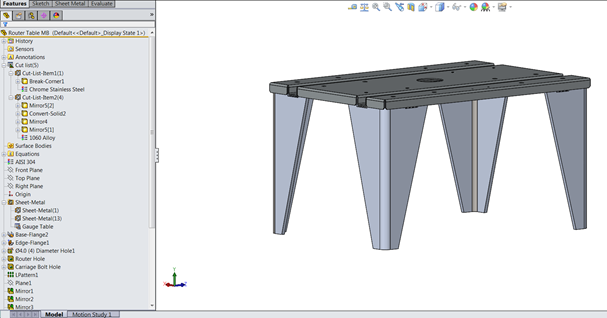
Here’s an example of what a multibody sheet metal part looks like. This is a
router table with a top and 4 legs:

In this example, the router table is AISI 304 material while the legs are AISI
306. Also, the legs and the table top are different gauges. Let’s step through
how you would create a part like this.
I’m going to start at the step where the table top was created as a single
body. To summarize, this was created as a profile sketch, extruded as a Base
Flange/Tab, and then Edge Flanges were added to the sides. There’s also some
holes added to the part:
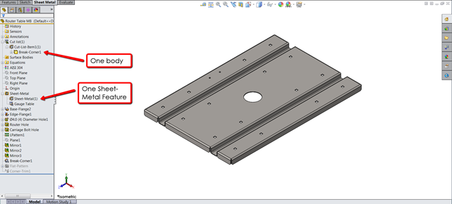
From the feature manager tree, we can see that there is one body in the Cut
list, and one sheet-metal feature, as expected since this is a single body
part. I’m going to start a sketch on one of the inside faces that will be the
profile of one of the legs:
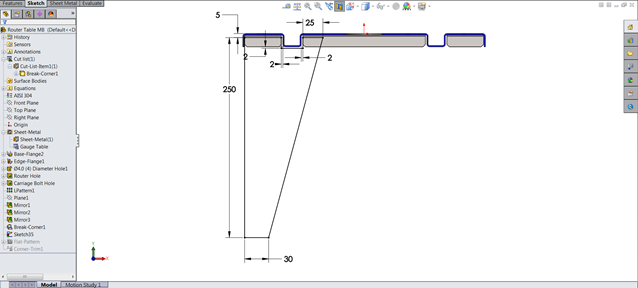
Note that the view has been sectioned so that we can make dimensions and
relations to the profile of the table. Now I will revolve the profile about
the long side 90 degrees:
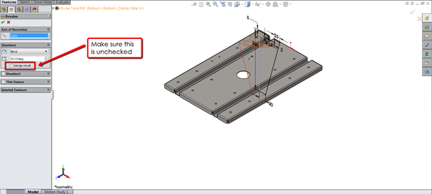
By default, SOLIDWORKS will want to merge this new feature with the table top
since they are touching (remember the first paragraph of this article?) I
don’t want it to do this since I want a separate body, so make sure that the
Merge result box is unchecked. Now if we look at the Cut list folder, there
are 2 bodies. I can also isolate the body I want to work on by right clicking
the name in the Cut list folder and clicking Isolate:
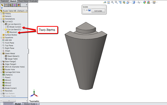
The icons are different since the first body is a sheet metal body and the
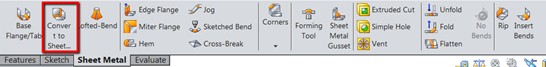
second body is a solid body. Next, we convert the solid leg to sheet metal by
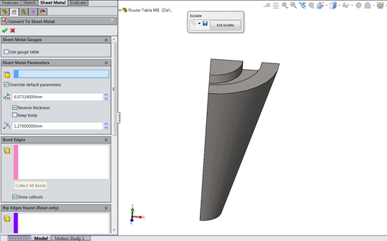
clicking the Convert to Sheet Metal button:
 At this point, we can choose to use the same gauge as the table or change
it:
After the conversion and exiting the Isolate, we now have two separate pieces:
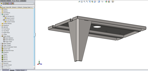
We can add different materials to each (right click on the body in the Cut
list, and if you look down at the bottom of the Feature Manager tree, you can
see we have two separate flat patterns:
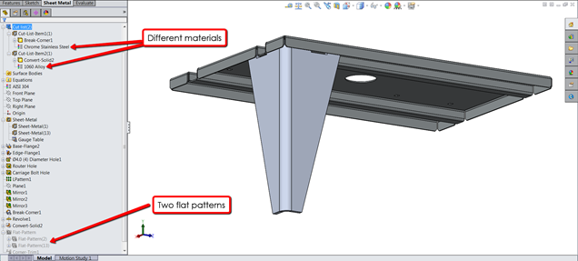
If you hit the Flatten button in the Command Manager, it will
only flatten the first body, so you will need to actually unsuppress the flat
pattern feature for the other body, or right click on the body and select
Flatten. Now with a couple of
Mirror operations, we can use that first leg to create 3 more
legs. SOLIDWORKS might add these bodies to a new Cut list, so just select them
and left click and drag them into the Cut list you want them to be in.
That’s it! If you would like to see a video on this, please click on this link. Good luck on your sheet metal designs and thanks for reading!


