
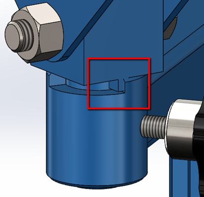
You have your design assembled in SOLIDWORKS and you go to move components to
test the functionality. Then you notice that some of the components are not
constrained properly as they’re allowed to move in a way that results in
intersecting geometry (see image below). This obviously wouldn’t happen in
real life. What now? There are a few mate types that allow you to restrict the
motion of these components to simulate real world motion. One of these mates
is the Limit Angle Mate.
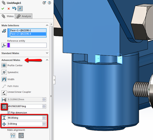
The Limit Angle Mate is an advanced mate type that allows you to specify a
range of angular values that a component is able to move. To access the Limit
Angle Mate, select Insert > Mate or click on the
Mate icon in the CommandManager. In the Mate PropertyManager,
expand Advanced Mates and select Limit. From
here, you can select the entities to mate, and input a Maximum and Minimum
value for the angle to specify the desired range of movement. Note that the
Angle box next to the Limit button is automatically populated with the current
angle between your selections.
In this example we have the two highlighted faces selected as seen in the
image below. We want this pin positioned to rotate within the slot. The
maximum angle between these two faces when the part is rotated until it hits
the other wall is 90 degrees, so we’ll input 90 for the maximum and 0 for the
minimum angle.
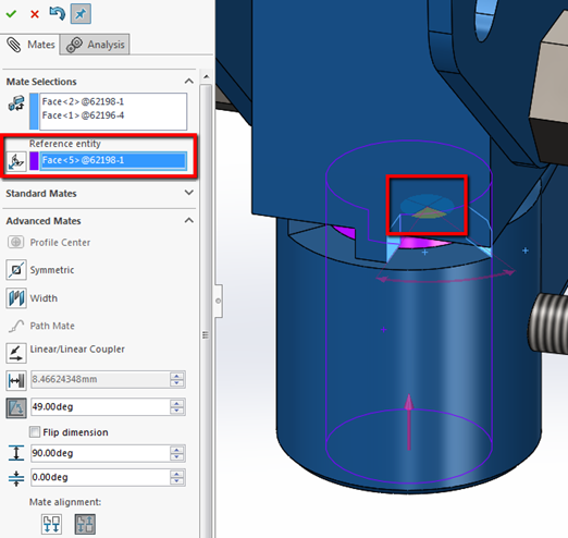
A nice enhancement that was implemented in SOLIDWORKS 2015 is the option to
include a Reference Entity. Reference entities help prevent
the Angle mate from flipping to the opposite side when moving the component,
as it defines an axis of rotation. You can then use the Dimension selector to
choose the quadrant where you want the dimension applied. This reference can
be selected manually, or click the
Auto Fill Reference Entity button to have SOLIDWORKS choose
it for you.
There you have it! Now all you have to is move the component to ensure it only
moves within the desired range, as it would in the real world. Hope you found
this blog useful. Be sure to check out our
YouTube channel
for more great tips and tricks!


