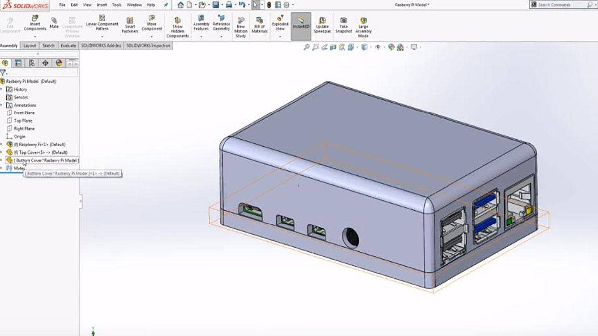
Have you ever been in the process of designing a new component that is associated with an assembly and realized the need to constantly jump back and forth between that part and assembly in order to measure critical areas of where that part should be positioned? If so, you may be able to benefit from using an in-context design process.
In SOLIDWORKS, in-context design refers to anytime you have two separate parts that are linked in an assembly through relationships or applied features. In this blog, we will look at how to model with in-context design elements so that your parts will automatically update and change with other parts inside of the assembly.
Creating In-Context Relationships
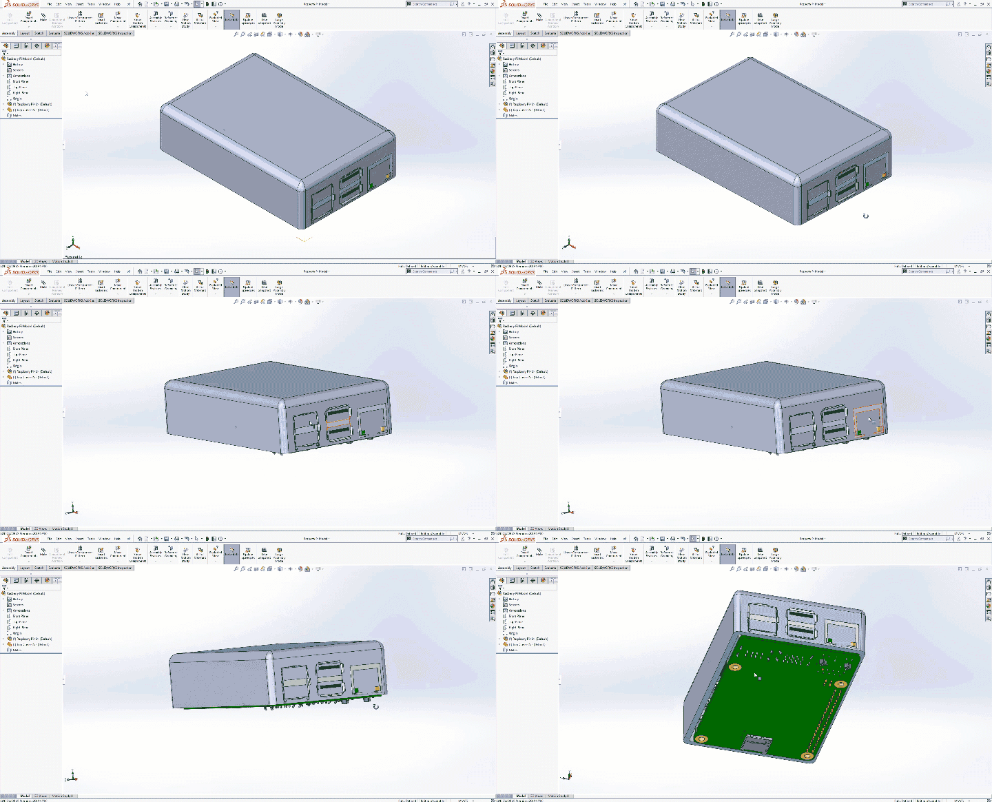
The first step to creating in-context relationships is to begin inside of an assembly. In this example, we will be designing a case for a raspberry pie. The top cover has already been created, however, no cutouts were established for the external ports. These cuts could be created using the measure tool and applying the dimensions found to a new sketch. Though effective, this method is time consuming and could lead to errors if sketches are not updated when parts change. Instead, we will use the existing part as a template and reference edges off of it to create the new sketch.
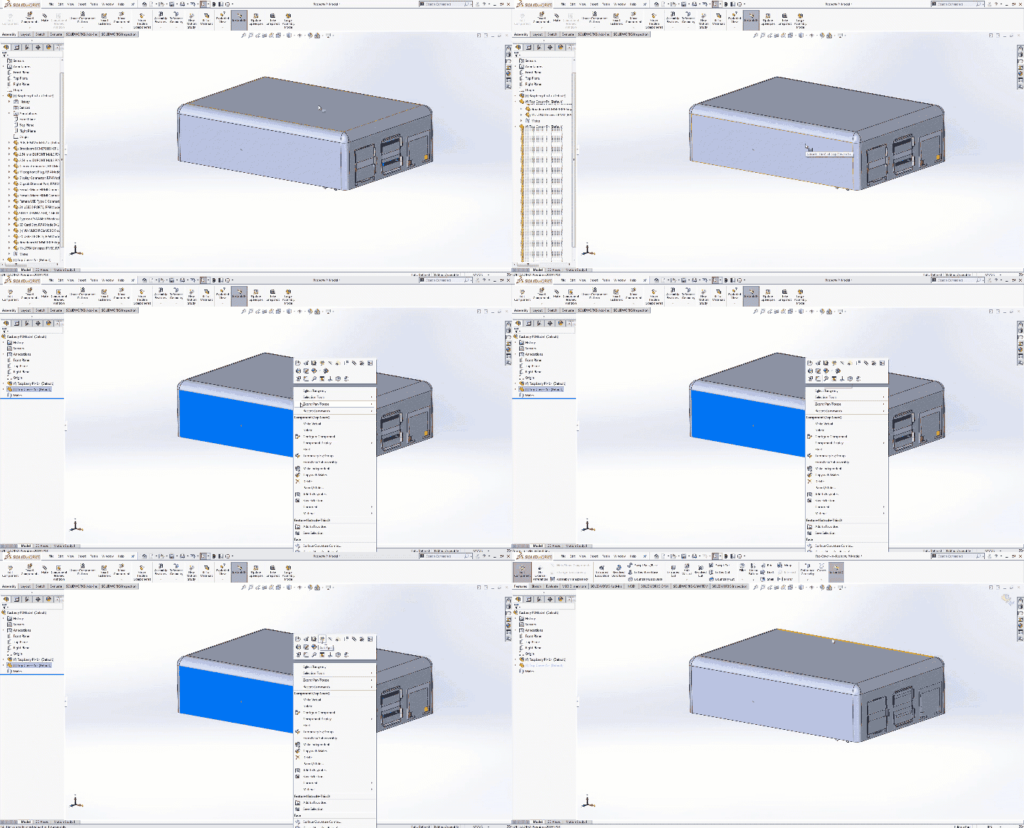
To Edit a part inside of an assembly, simply right click on the desired part and select Edit Part. The command manager will change, removing the assembly tab and replacing it with the features tab. All normal part features are now accessible at this point, allowing you to create your features while also referencing the part in the background.
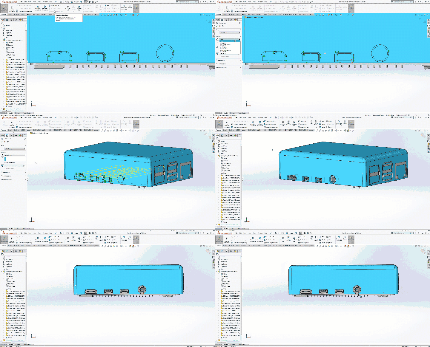
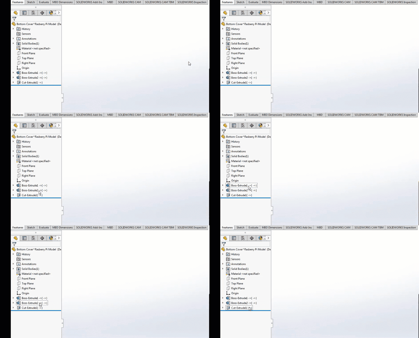
We will start by creating a new sketch on the side face. Inside of this sketch, all of the external ports will be selected using the intersection curve. This selection will create an On Edge relationship that is driven directly back into our assembly and ultimately the original raspberry pie part model. Once this relationship has been created, we will continue by using standard modeling techniques. The only difference that will be visible between this feature and one that was not made in the context of an assembly are the in-context relationship symbols that appear next to each feature.
Existing parts can easily be edited and changed, but in-context design methods do not stop there. Brand new parts can be created inside of an assembly as well by clicking on Insert Components>New Part.
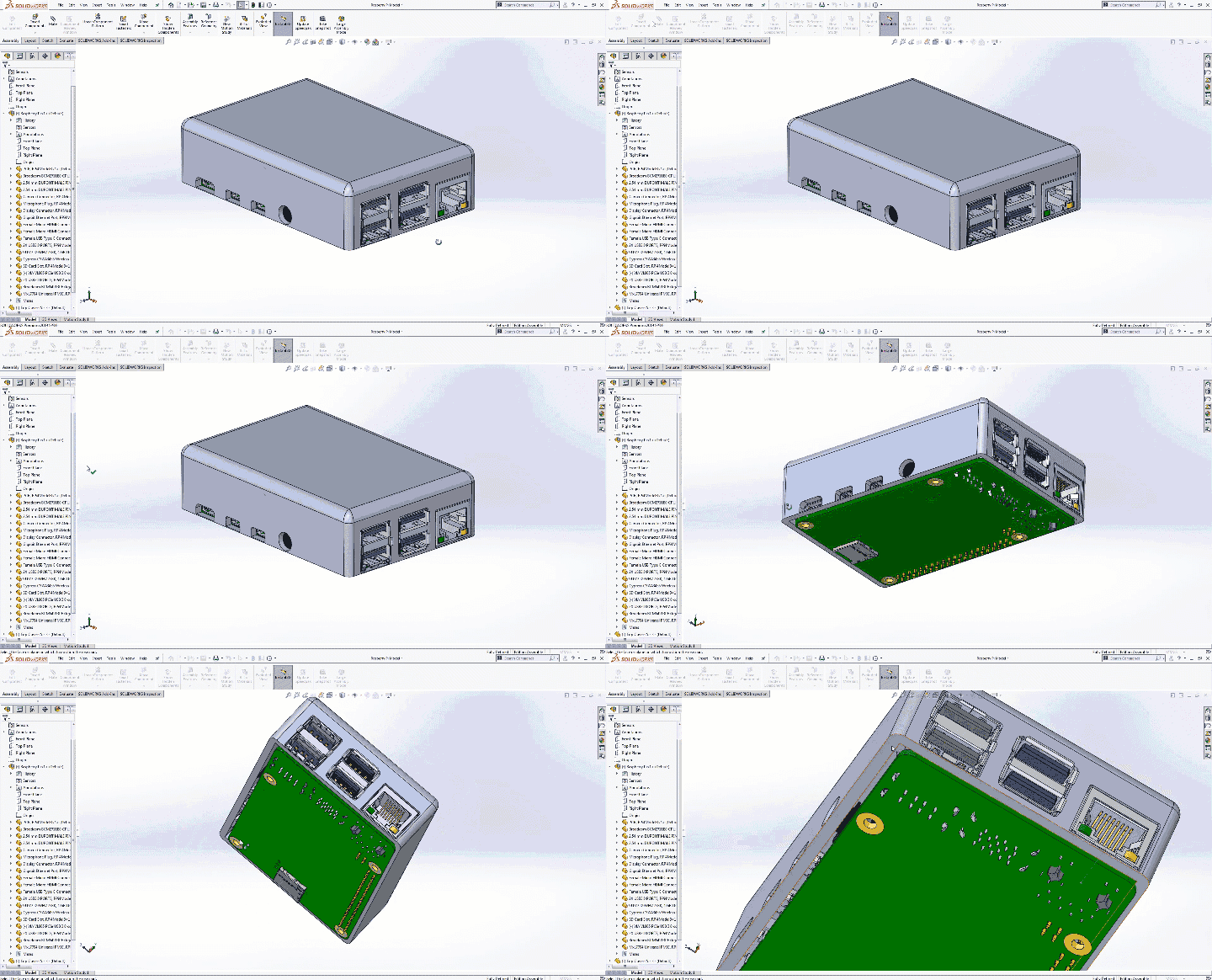
After selecting New Part, notice the command manager will become grey. This is because SOLIDWORKS needs you to select a plane to position this new part. In this example, the bottom face of the top plate will work nicely. Based on the selected face, a new part will be created, oriented in the Front Plane.
You can begin creating any required features as you normally would in a standard part file. These new features can be linked into the existing assembly or created using standard dimensions while visually referencing the assembly in the background.
Using an in-context design for your next project can save a significant amount of time not only in the initial design process, but also when it comes to editing and making changes to your project. For more information or if you have any questions, contact us at Hawk Ridge Systems today. Thanks for reading!