With today’s smart and connected products, an increasing amount of design projects involve incorporating mechanical, electrical and electronic elements – with PCBs, wires, cables and harnesses making up key elements of the design.
One of the most challenging parts of the design process is creating cables and harnesses within the digital 3D model. Representing these shapes presents a complex modeling task, and for many companies, cables and harnesses are left out of the digital 3D model. This lack of documentation can lead to issues with manufacturing errors, or unnecessary prototype and revision cycles.
Wire Harnessing Design Problems
There are methodologies available within SOLIDWORKS, particularly using the Electrical Routing modules, to model the wire routes that make up a harness, but using these techniques requires a deep understanding of 3D mechanical CAD, and the rules and processes that go into modeling. Many of the users tasked with wire routing come from an electrical or electromechanical background, and may not have the SOLIDWORKS experience to be able to navigate mates, 3D sketches and discerning between part and assembly context to perform this work efficiently.
Faced with these challenges, many companies have fallen back to only creating 2D manufacturing drawings of wire harnesses in software tools like AutoCAD or Visio. This has been common practice in the industry for many years, but doesn’t offer many of the benefits of working in 3D, including:
- Accurate wire length information without needing to prototype or manually measure
- Precise weight and space allocation with harnesses modeled in the system
- A model responsive to design changes that allows wire harnessing to be designed earlier in the design process, parallel to the mechanical design
Our Hawk Ridge Systems team spent the last couple of years looking for a better way to perform this work, and we believe we found the ideal fix.
The Perfect Wire Harnessing Solution
We now utilize a SOLIDWORKS partner product called Enterprise Harness, produced by Landmark Technology. Enterprise Harness is a powerful, easy-to-use 3D modeling package exclusively designed for wire harnesses, and is unique in the market in its approach to the design process.
Harness design workflows in Enterprise Harness start with two key pieces of input information:
- The 3D CAD model, exported from SOLIDWORKS with a single click in the SOLIDWORKS interface. This generates a lightweight version of the model, improving performance as these models can be large.
- A From/To list summarizing the pin-to-pin connections the harness needs to make. This can be exported from schematic design software (we recommend SOLIDWORKS Electrical), or manually created in Excel. Harnesses can be created without a From/To list if needed.
Within the Enterprise Harness interface, connectors identified in the From/To list are then placed by the user in the appropriate spots in 3D space. The software features a connector library, and harness connectors will automatically snap to their matching partner without having to manually mate.
Once connectors have been placed, the wire routing is mapped out, with simple clicks to set the start and end points of the route, as well as any intermediate points needed. The path of the 3D route can be manipulated at any point with simple push/pull controls, and branches can easily be created, again just by clicking in the model. This is easier than approaches in SOLIDWORKS Routing, which can involve managing and manipulating complex splines.
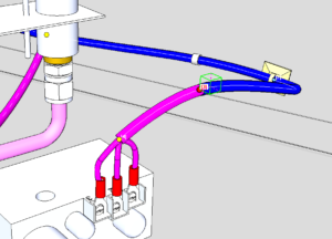
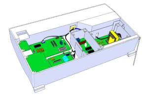
Individual wires running from pin to pin are then automatically added, reading that information from the From/To list, and once the harness is complete, a single click sends the finished 3D shape back to the original SOLIDWORKS model.
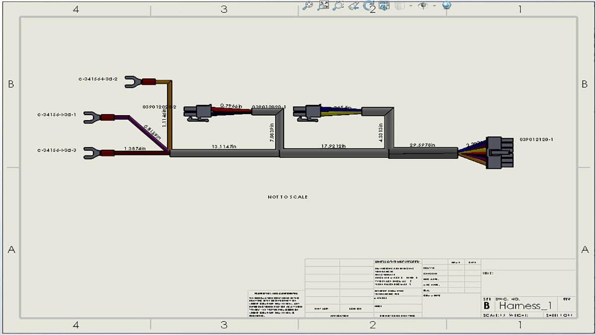
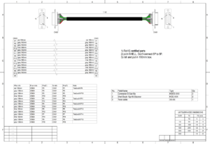
Harness drawings are created in the companion Enterprise Layout environment, and there are two main visual styles available, either a schematic layout of the harness or a manufacturing drawing that represents the true shape. Summary tables for the bill of materials and From/To connections are also available.
When the design changes, as it almost always will, any type of change can be accommodated with a model update. If the electrical circuits change, the From/To list can be re-read, and changes to the 3D model will update with a single-click in the SOLIDWORKS interface. Users control exactly when any design changes are propagated, which helps to manage the change process.
Overall, Enterprise Harness is a software package that allows for quick, intuitive modeling of 3D wire harnesses, is accessible to users who aren’t experts in 3D mechanical CAD, and provides a complete digital model of the electromechanical design, with all necessary manufacturing documentation.
Contact us today to learn more about Enterprise Harness. Thanks for reading!