 Since the advent of
CAD software
in the design and engineering world, one of the main advantages touted by
developers and users has been the ability to check for errors and mistakes
during the design process. Discovering and fixing design flaws, honest
mistakes, and little bugs before a product reaches the production
phase – not to mention consumers – is an obvious way for a company to reduce
costs, waste, and protect themselves both from lawsuits and a bad reputation.
There is almost no disputing the fact that computers scanning for and
rectifying human mistakes during the design process has led to an overall
improvement in the general quality of the products we use in the world today,
and major savings for the companies that make those products.
SOLIDWORKS Electrical is no exception to this trend in engineering CAD
software. There’s an obvious need to be able to rapidly scan and check
electrical project documents for accuracy, completeness, and informational
clarity: with potentially thousands of wires going to dozens or hundreds of
components, it’s almost a statistical certainty that there will be
errors and small inconsistencies in the drawings and schematics.
SOLIDWORKS Electrical
takes care of this inherent problem by including several Design Rule Checks,
commonly referred to as DRCs. These DRCs scan the project for specific errors
and then provide a report on what those errors are and where they appear in
the project for a variety of different potential issues.
 In this 5-part blog series, we’ll go in depth over four of the most commonly
used SOLIDWORKS Electrical DRCs – what they are, how they work, and why you
would use them – on top of this introductory overview. These four DRCs are
also demonstrated in a 4-part YouTube video series. (Watch the first video
here.)
So, what exactly is a DRC and how does it work? A DRC is just a standard
report template that’s included with the software and designed to scan the
project for certain data criteria in the SQL database, then report back
anything that matches that criteria in the database in an easy-to-read format.
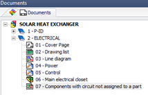
For example, if the DRC is selected to scan for Components without Part
assignments, the software will look through the Component list in the SQL
database and find any Components that do not have a manufacturer part assigned
to it, and then generate a table showing the Component tag and its location in
the schematics. This table document is then added in the master documents list
as a report; it can be saved as part of the revision and verification process
to include as documentation, or can be deleted once the errors are fixed.
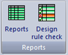
SOLIDWORKS Electrical, they can be accessed in the CommandManager in the
same location as Reports. To see the list of included DRC templates, click
on the Project tab and in the far right section titled
“Reports” is the Design Rule Check icon.
Click it and click Add in the upper left corner of the Design
Rules Manager window to see the master list of all the DRC templates included
with SOLIDWORKS Electrical.
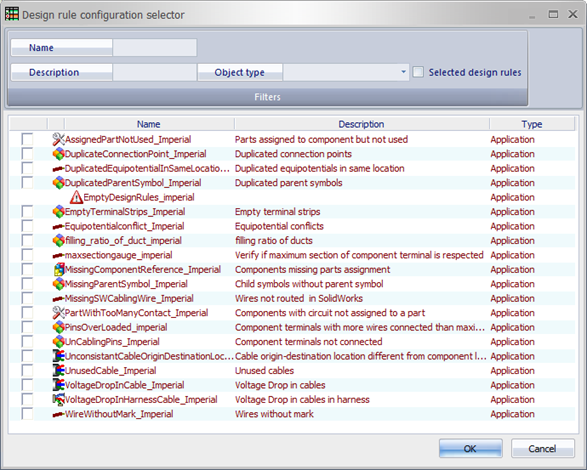
To use any of the DRCs in the list, simply check the box next to the design
rule you’d like to implement and click OK; the software will
begin its scan of the project, and generate a report in the documents list if
any errors are found.
Be sure to check back for the follow-up blogs in this series, where take an
in-depth look at the Equipotential Conflict, Component Terminals Not
Connected, Components Missing Part Assignment, and Parts Assigned to Component
but Not Connected DRCs. For a visual demonstration, you can check out our
SOLIDWORKS Electrical series for Design Rule Checks on YouTube.
