Sometimes the vast library of weldment profiles included with
SOLIDWORKS just doesn’t have the special profile I need for my project. I was mocking
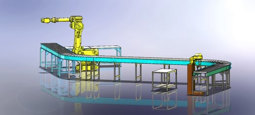
up a layout of a conveyor system for a shop the other day that I planned to
use a purchased conveyor system for the design, and wanted to figure out the
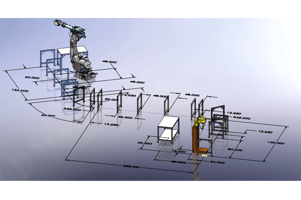
amount of conveyor rails I would need. In SOLIDWORKS, I used a layout sketch
in an assembly to define the parameters of the shop by importing the floor
plan into the layout sketch, inserting blocks that represented the machines
and workstations, and adding sketch entities to define the path the conveyor
would meander through the shop.
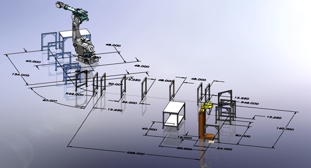
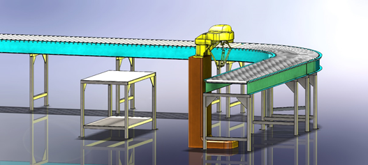
Once the layout was defined, I then inserted the machines, work benches, and
structural frames that would serve to support the conveyor system into the
assembly, mating them to the blocks and sketch entities of the layout sketch.
(Parametrically speaking: the layout sketch now can be modified to locate
everything in the shop, including the lengths and orientation of the conveyor
system.)
Once the models were placed in the layout sketch, it was time to place the
rails of the conveyor on the supports. I needed to create a custom weldment
profile to represent the rails. The system I was planning to use provided me
with the necessary specifications of the rails and my approach was to use
weldment cut list in SOLIDWORKS to help me define the amount and lengths of
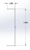
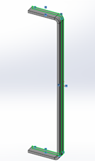
the rails that I would need. The system uses 12 gauge formed steel C-channel
for the rails that measure 1.5” X 7”.
Here’s how I created the custom weldment profile:
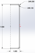
I sketched the initial geometry in a SOLIDWORKS part, then turned it into a
sheet metal part using the 12 gauge selection from the gauge table in
SOLIDWORKS.
![]() I selected the end faces of the sheet metal part and converted the edges to
I selected the end faces of the sheet metal part and converted the edges to
a new sketch.
![]() Then using [CTRL-C]/[CTRL-V], I copied and pasted this into a
Then using [CTRL-C]/[CTRL-V], I copied and pasted this into a
New Part File, and using Fully Define Sketch in SOLIDWORKS, I fully defined the profile.
modifying an existing weldment profile, careful consideration is taken for
how the profile might be used. When a weldment profile is inserted into a
sketch for creating structural members in the weldment part,
SOLIDWORKS locates the profile using vertexes in the geometry. A sketch
point must be inserted in the profile for insertion points that are not
located at a vertex. In my example here, I have added a construction line
with a sketch point at the midpoint, for illustration purposes.
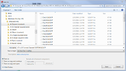
The final thing to do is to save the sketch as a Library Feature part. The
following steps need to be taken in order to ensure success:
-
Select the sketch that contains the desired geometry in the Feature Manager
Tree. - Select File, Save-As, and select Save as Type: Lib Feat Part (.sldlfp).
-
Browse to the folder that holds your current SOLIDWORKS Weldment Profiles,
or a folder that you have specified. (The later choice requires that you add
that folder path to the Weldment Profiles search path in Tools, Options,
System Options, File Locations, Weldment Profiles).
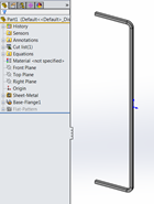
When completed, the Feature Manager Tree in the Lib Feat Part should look like
this image:
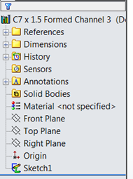
Notice the icon at the Top Level of the tree, it indicates that this is a
Library Feature. Also, notice the icon of the Sketch1 at the
bottom of the tree, it has a green “L” superimposed on it. This is a
result of selecting the sketch first before
Saving As a Lib Feat Part.
THIS IS VITAL IN ORDER FOR THIS TO WORK AS A WELDMENT PROFILE.
I chose the approach of converting the edges of a sheet metal part for the
basis of the profile because sometimes, you may find an extrusion or
something downloadable from an online source and want to use that as a
weldment profile. This example demonstrates how to do that.
Now that the weldment profile is ready to use, I return to my assembly and
insert a New Part to be created “In Context” of the assembly, and use my new
profile to layout the rail sections in my shop mock-up. Because these are
weldment parts, I am able to use the cut-lists to determine how much conveyor
I will need. Because they are created in the context of the assembly, I can
use the Layout Sketch to size and position my shop to a configuration that
will work – before I spend the money on my conveyor.
You may also want to check out this blog my colleague Holly Cheek wrote about
configurable weldment profiles.


