
pattern available for setting up patterned components along an open or
closed path. This is perfect if you want to dynamically simulate roller
chains, cable carriers, and power transmission systems.
Energy Chain with Rotary Motion
The previous example would work great with some type of gantry with linear
motion. In this case, what if the motion is more circular or rotational than
linear?

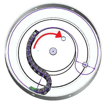
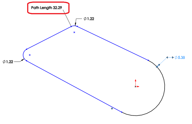
Well, it’s all in the sketch path that drives the Chain Component Pattern. You
aren’t limited to sketches only consisting of lines and arcs for the chain
path. You’ll notice that this case requires 3 arcs in the path: one that
defines the outer diameter (or the outer ring), one that defines the inner
diameter (or the hub), and a small arc that represents the bend or return
between the two.
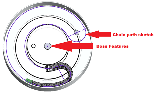
Now in order for this to behave properly, the “dummy” component that contains
the chain path sketch must be properly constrained in the assembly. For the
correct rotary motion, the component must be concentric to the ring and hub
components and, in this case, constrained to the hub so that when the inner
hub is dragged (rotated), the chain path moves with it and therefore drives
the Chain Component Pattern to move with it. (See below.) Extra features such
as bosses and/or reference geometry may be needed in the chain path sketch
part to allow you to mate things together as desired.
Closed Loop Chain
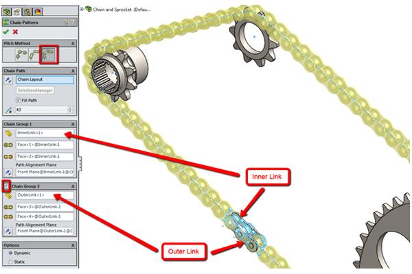
Now let’s take a look at a perfect example of a closed loop chain. This one
has another interesting twist as unlike the energy chain, which uses a single
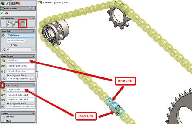
type of link, a bicycle chain has two types of alternating links.
When we set up this feature, we’ll need to pattern both the Inner and Outer
Links that alternate to make the chain. We’ll use the “Chain Group 2” option
and selections to accomplish this.
Something else to consider here is that in reality, the final link in the
chain would be attached to the first link in order for it to be a closed loop.
However, we cannot create the mate to accomplish that in SOLIDWORKS. So, how
do we make sure the total length of our path is correct so that the final link
does indeed meet the first one?
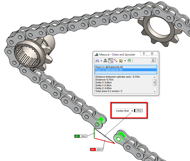
The trick here is to determine the total number of links you want and use the
“Fill Path” option. Once this is done, you can measure the remaining gap
between the first and last component. Using the Path Length Dimension, adjust
the sketch path by that amount to close the gap.
In-Context Chain Path Sketch
There are applications where the movement of the chain is dependent on the
position of other components in the assembly to which the chain is attached.
This is easily done by creating an in-context sketch constrained to the moving
component, in the chain sub-assembly.
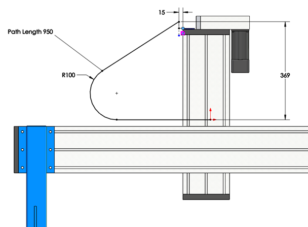
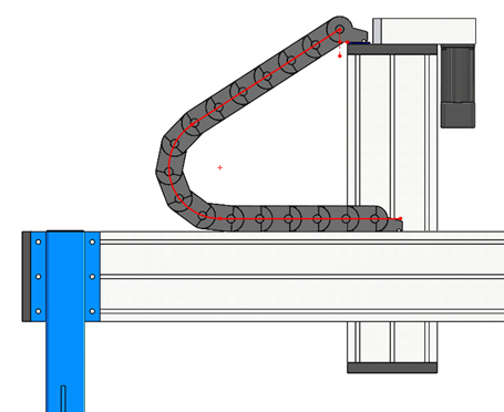
In this example we have a gantry system where the chain path sketch is defined
in the context of the assembly to the vertical head component. Notice the
angle of the path is not specified; it is dependent on the position of the
head component.
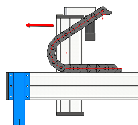
Now, there is one difference in the behavior of the chain movement when using
in-context referencing for driving the chain path. When the component (the
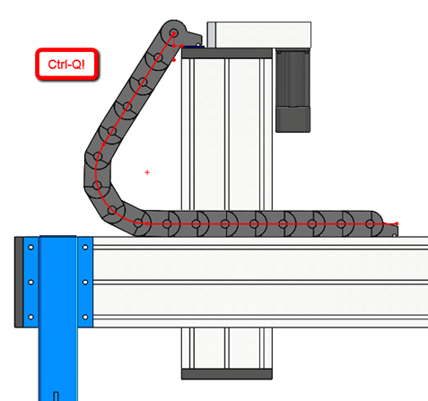
head) is moved, the chain motion will not be real-time. The top level assembly
MUST be rebuilt so that the chain path sketch is solved for the new location
of the component, which then allows the chain component pattern to be solved.
This is still very useful for positioning information in your design and
drawings.
In part 3 of this series, we’ll take a look at special considerations
regarding optimum behavior and performance when using the Chain Component
Pattern in
SOLIDWORKS 2015.


