
The previous article discussed capabilities of SOLIDWORKS useful for the
woodworking industry on an example of a set of frameless cabinets. This
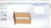
article and companion video will discuss the design of framed cabinetry in
SOLIDWORKS as well as some additional modeling details, on an example of a
simple set of drawers:
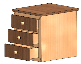 |
Worth noting is that the motion of drawers, doors or nearly any hinged or
sliding mechanism can be simulated in a SOLIDWORKS assembly to check for a
range of motion and interferences.
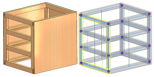
Focusing on the cabinet itself, we can see that it is made up of 1x2s. An easy
way to represent these types of framed structures in SOLIDWORKS is to use the
Weldments “Structural Member” tool.
The structural member tool was originally intended for large steel framed
structures but has also found popularity in other applications such as
woodworking, as users can easily define their own profiles for stock material
sizes. This tool allows assigning of the desired profile to a single-line
outline sketch and performs automatic trimming of the various members against
each other.
 |
Also of importance is the automatic creation and tracking of a cut list. Any
members created with the Structural Member tool automatically have their cut
length tracked and identical cut items grouped together, allowing the user to
quickly generate a cut list for shop drawings.
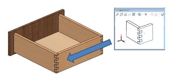
Focusing down on the level of an individual drawer, repetitive design tasks
such as joinery features can be automated through the creation of “Design
Library” features such as Smart Features and Smart Components. These allow the
user to define SOLIDWORKS features on a dummy part, which then allows dragging
and dropping the desired features onto the current design. A preview window
guides the user through selecting any references necessary to associate the
feature.
 |
Smart Components establish a similar functionality at the assembly level. One
application of Smart Components would be to allow a user to place a piece of
hardware such as a hinge, and automatically propagate the hole pattern
necessary for the hardware, as well as insert any required fasteners.
For more information, check out our
YouTube channel
or contact us at
Hawk Ridge Systems
today. Thanks for reading!


