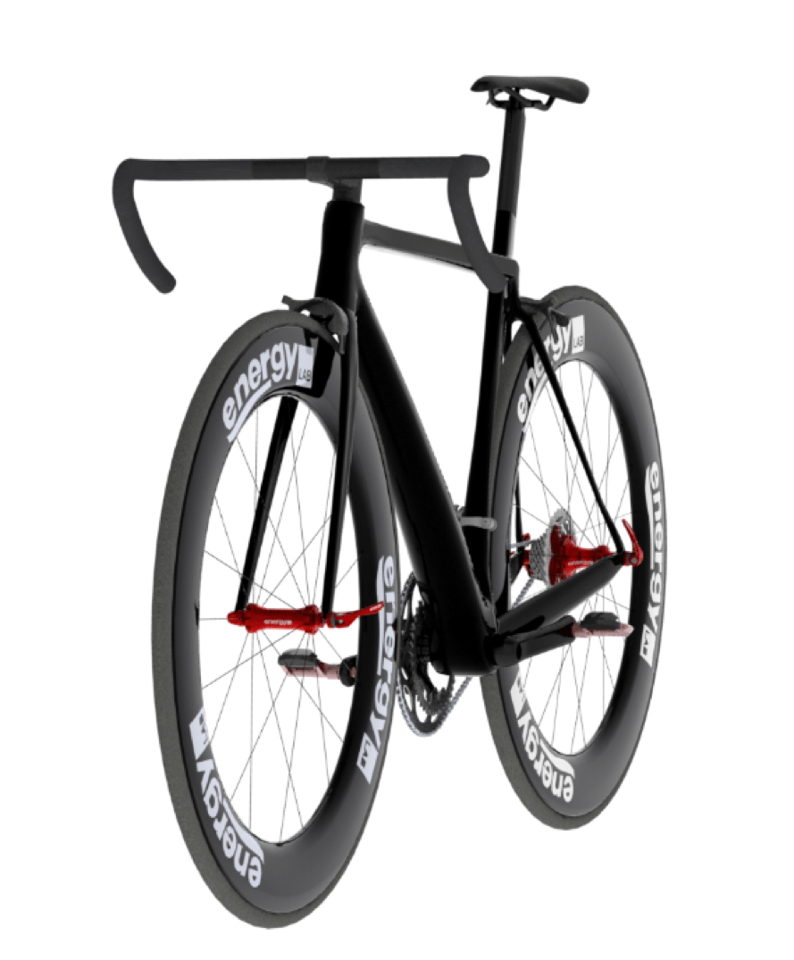

In this series, I will design a racing road bicycle with the help of
SOLIDWORKS. Starting with the geometry, I will move on to the tube shapes and
componentry to come up with an engineered speed machine. What’s to come?
Part 1: Frame Geometry Optimization; Using 3D Sketches, Weldments, and Static Analysis to optimize the frame
geometry.
Part 2: Tube Shape Optimization 1; Using Surfacing and Static Analysis to define the shape of the tubes.
Part 3: Tube Shape Optimization 2; Using CFD analysis to
optimize the aerodynamic efficiency of the tube shapes.
Part 4: Components and Details; Finishing up the rest of the
bike. Because why not?
Part 3: Tube Shape Optimization 2
In this part, I will be using SOLIDWORKS Flow Simulation, the fantastic
computational fluid dynamics (CFD) tool available for SOLIDWORKS, to further
improve the design of the bicycle frame by improving its aerodynamic
efficiency. Before getting into the analysis, I need to clarify what I mean by
‘aerodynamic efficiency’, and define which parameters I will focus on to
improve it. If you consider a moving frame of reference with a velocity equal
to that of a moving bicycle, then you can analyze the bicycle as a stationary
body immersed in a free stream of air. In this type of analysis, it is
customary to define an axis parallel to the free stream. The force exerted on
the body along the free stream axis is called drag. Drag must be overcome in
order to move against the free stream. Therefore, in order to be more
efficient, one must reduce the drag of the body. So, aerodynamic efficiency
can be directly linked to drag. Lowering a body’s drag will increase its
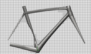
aerodynamic efficiency. Set Up The analysis will start with
just the frame. This is done to set a benchmark level of performance about
which I will calculate improvements.
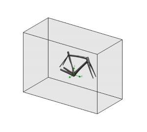
As can be seen in the figure above, a ‘box’ around the frame represents the
computational domain of our analysis. This domain will be analyzed using the
Finite Volume Method, by which the volume is partitioned into smaller cells
for ease of calculation (the smaller & more numerous the cells, the more
accurate the result), I will discuss mesh refinement later on in this blog.
The X- axis will be used as the free stream direction.
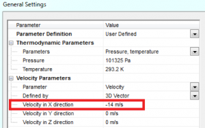
Using ambient conditions (standard atmosphere), I will define the free stream
velocity as 14 m/s (50kph), which will be kept constant throughought the
entire analysis.
Before we start the solver, we need to input some engineering goals. This is a
great way to gather relevant data and ensure convergence of results.
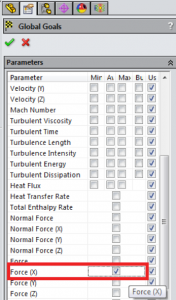
By setting a global goal of Maximal Force in the X-direction (which is our
Drag) we can easily find out what that value is and, as a bonus, watch a nice
convergence plot while the solver is running.
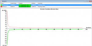
The above chart (taken while the solver was running) shows that the drag force
value had converged at 4.16 N, which is our benchmark value.
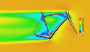
Preliminary Analysis By inserting a Velocity Cut Plot, we
can get a better idea of the flow behavior. Ideally, the range of flow
velocities would not be large.
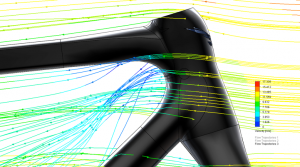
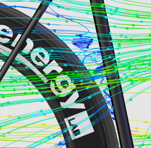
We can also create a Flow Trajectory Plot, which will allow us to identify
areas of turbulence and unsteady flow behavior.
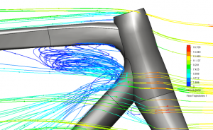
This reveals some trouble areas near the head tube and seat tube (it’s
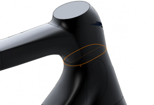
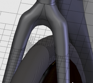
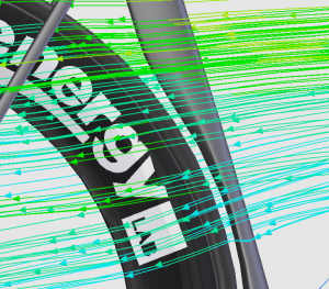
hilariously bad). Head Tube Optimization Going back to the
profile of the head tube and incorporating a more streamlined and airfoil
shape, the flow behavior is drastically improved.
The new drag force was 3.658 N (a 12% reduction in Drag).
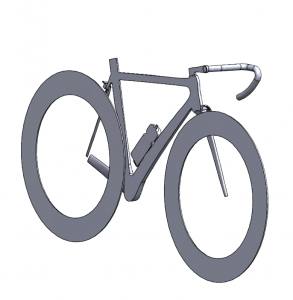
Geometry Check Now that the benchmark is set and the first
improvement was incorporated, the frame will be analyzed with all of the
bicycle’s crucial components. This will give results that more accurately
reflect real riding conditions as well as give us some interesting insights.
When conducting a flow analysis on an assembly, or complex part, it is
important to incorporate a geometry check to ensure the study is set up
correctly.
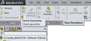
The Check Geometry tool allows you to calculate the fluid volume, as well as
create a part file of the body that is to be analyzed.
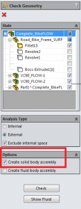
For this analysis, the frame, wheels, and bottle were all hollow. However,
these cavities would not affect the external flow analysis, so we would expect
them to be solid to ensure faster processing times.
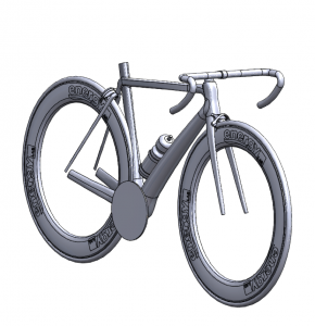
As can be seen in the image above, the cross section of the solid body
assembly reveals that the body is indeed solid and does not include any
unwanted cavities. This saved time and ensured accuracy.
Mesh Refinement Now that we are incorporating more
components, we need to go back and analyze the body to enhance the mesh and
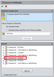
ensure accurate results. A method that I like to use for external flow is
based on the narrow channels featured in your geometry. Ideally, you would
like to have 3-4 fluid cells across each channel. This can be done by first
conducting a Clearance Verification to calculate the smallest gap in your
geometry.
Then setting that value as the minimum gap size in the Mesh Settings of your
Flow study.
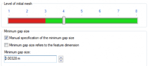
The refinement slider can then be altered until the mesh is satisfactory.
Focused Analysis When analyzing more complex scenarios it can
be difficult to discern how individual components, such as the bottle, are
affecting the flow. To get around this problem we can create trajectory plots
of flow that comes in contact with specified faces. For example, I would like
to see how a water bottle would affect the flow characteristics. So, when
creating a Flow Trajectory plot, I can select the component and activate all
of its faces in the input for starting points.
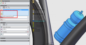
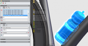
This ensures that I only see flow trajectories that are in contact with the
bottle.
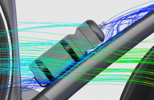
Analysis of the results showed that the bottle had negligible effects on the
Drag (< 1%). This is likely due to the wide downtube, which was designed
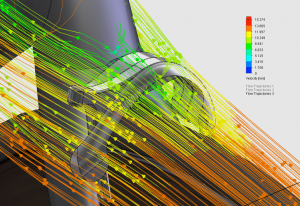
specifically to accommodate a bottle. Rear Cut Out It is
often said, by bicycle manufacturers, that a rear wheel cut out ‘smoothens
airflow from the frame to the wheel.’ Let’s test that claim. An analysis of an
identical frame, except for the cut out, showed turbulent airflow between the
frame and rear wheel.
The cut out promotes much smoother airflow, reducing drag by 4%.
Hidden Brakes Another trend happening in the world of
‘aero-bikes’ is the idea of hiding the brake calipers underneath the frame or
behind the fork. How much do brake calipers affect the drag? Is it worth
loosing braking performance? Let’s find out!
According to my analysis, the bakes account for a 0.42% increase in Drag. In
my opinion, I could live with the tiny increase in Drag if it meant I didn’t
have to sacrifice braking performance. Table of Results
| Feature | % Change in Drag |
|---|---|
| Head Tube Design | -12 |
| Bottle | 0.1 |
| Rear Cut Out | -4 |
| Hidden Brake Calipers | -0.42 |
Thank you for reading. For more content like this, check out our other great
blogs and videos!


