In this series, I will design a racing road bicycle frame with the help of SOLIDWORKS. Starting with the geometry, I will move on to the tube shapes and componentry to come up with an engineered speed machine.
What’s to come?
Part 1: Frame Geometry Optimization – Using 3D Sketches, Weldments, and Static Analysis to optimize the frame geometry
Part 2: Tube Shape Optimization 1 – Using Surfacing and Static Analysis to define the shape of the tubes
Part 3: Tube Shape Optimization 2 – Using CFD analysis to optimize the aerodynamic efficiency of the tube shapes
Part 4: Components and Details – Finishing up the rest of the bike. Because why not?
Bicycle Frame Design Part 2: Tube Shape Optimization 1
This section deals with modeling the tubes of the frame. I’ll be using surfacing techniques within SOLIDWORKS to do so. There are some design elements that I’ll incorporate, such as a rear wheel cut-out and a tapered head tube. The impact on performance, such as stiffness, be tested to validate the design choices.
So let’s begin. As always it all starts with the sketch.
When designing with optimization in mind, it’s important to ensure you have a robust model. In other words, if you change the curvature of a loft path or edit a profile slightly, your model should rebuild without hemorrhaging errors. This is challenging to do when working with surfacing, but there are some tips that I can give (for SOLIDWORKS users) to help you achieve this robustness.
TIP # 1
Check that two contacting surfaces can be knitted. If there are issues, resolve them before continuing.
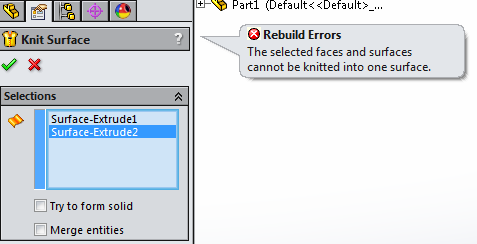
If you have a message like this, it is best to resolve it before adding more surfaces to your part. Fixing issues while you work will save you time (troubleshooting errors is easy when you know where they are occurring and if they are not deeply embedded in your part).
TIP # 2
Ensure permanent knit features are saved for the end of your modeling process (ideally, you should only have 1 at the end of your Design Tree).
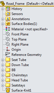
As you are creating knit features to check that you don’t have errors, make sure to delete them as you continue to work. When your design is complete, knit your surface bodies with one permanent knit feature. This will help to avoid issues such as surface copies (every knit creates a new surface), and will make life easier if you have to make changes to your part.
TIP # 3
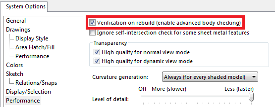
Activate ‘Verification on rebuild (body checking)’ within the Performance section of the System Options. This will help ensure you don’t have any faulty, erroneous geometry that would haunt you later.
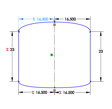
Profile-Based Design
Admittedly, I have never heard or seen anyone use or talk about ‘profile-based design’ so I’ll elaborate on what I mean.
The crux of my design will be based on the profile, or shape, of the frame tubes. These profiles will be connected to other profiles with lofted surfaces and guide curves.
It’s easy to see that performance is largely dependent on these profiles. Properties such as moment of inertia, aerodynamic drag, weight, and visual appeal are mainly based on the tube’s profile (think about I-beams, they aren’t called “long block” or “straight pipe”. It’s all about the profile). Furthermore, incorporating parametric design to surface techniques will enable me to enhance the design using engineering techniques rather than relying solely on artistic inclinations.
TIP # 4
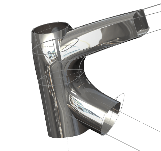
If you have two lofts that share the same profile there is a very easy way to blend them together. Consider the part of the frame where the seat stays meet the top tube.
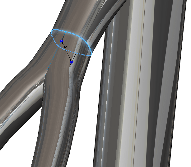
I modeled the left stay then mirrored the surface body about the front plane to get the right stay. Since I have a plane that is situated directly at the intersection point, I can use it as a trim tool to cut the redundant section.
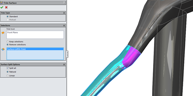
By doing this on both sides, I’m left with non-intersecting geometry that can be knitted together.
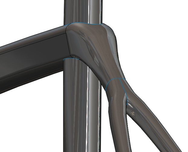
The same technique can be used for the fork as well.
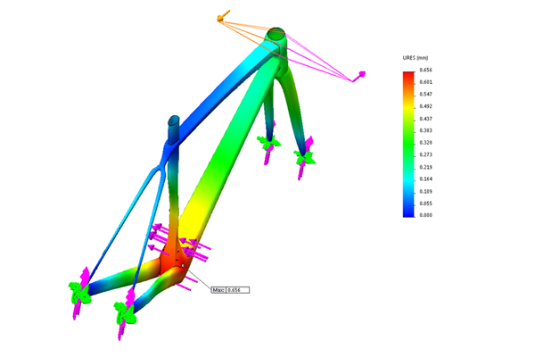
Once the basic geometry was created, the model was analyzed using a static analysis study.
Static Analysis
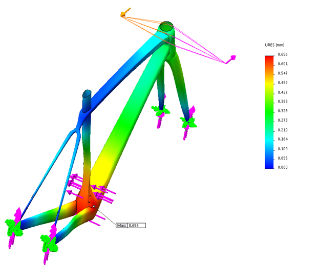
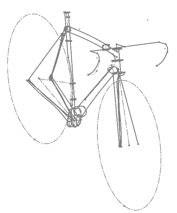
Force Diagram
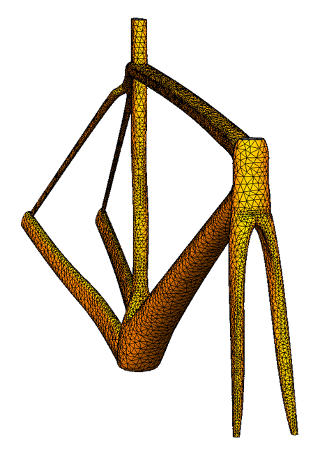
When we want to incorporate FEA techniques in our analysis, we should consider ways to simplify our model. A bike frame has a very small thickness relative to its surface area. Therefore, we can analyze the geometry using shells.
In SOLIDWORKS, shells are very easy to set up. With the help of the Shell Manager, surfaces can be given a thickness, material, offset type, and more within one convenient table.
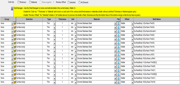
Analysis (computational) times are much lower for shells than solid geometry.
Furthermore, laminar edges (coincident surfaces) are treated as bonded, so there is no need to worry about knitting your surfaces before starting your analysis.
Tapered vs. Non-Tapered Head Tube
There is quite a lot of hype about ‘tapered head tubes’ in the performance cycling world [where the bottom profile of the head tube tapers out], but how much of a difference does it actually make? To find out, I ran a static analysis to see if there was any noticeable effect on the frame’s stiffness.
The main forces applied to the bike are torsional and lateral forces. Therefore, we can limit our analysis to torsional and lateral stiffness.
Stiffness is defined as follows:

Where
K = Stiffness
F = applied Force
δ = Deflection
Torsional Stiffness is defined as follows:

Where
K = Torsional Stiffness
T = Applied Torque
θ = Rotational deflection about torque axis
These are simplified definitions for a body with one degree of freedom. This can be applied to our case by analyzing the resultant deflection in the direction of the applied force as long as one force is applied at a time for each analysis.
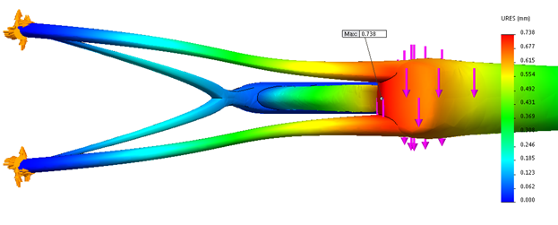
First, let’s look at the torsional stiffness. In order to calculate torsional stiffness (for the Head Tube) we can create a resultant plot of the circumferential deflection about the Head Tube Axis (HT AXIS).
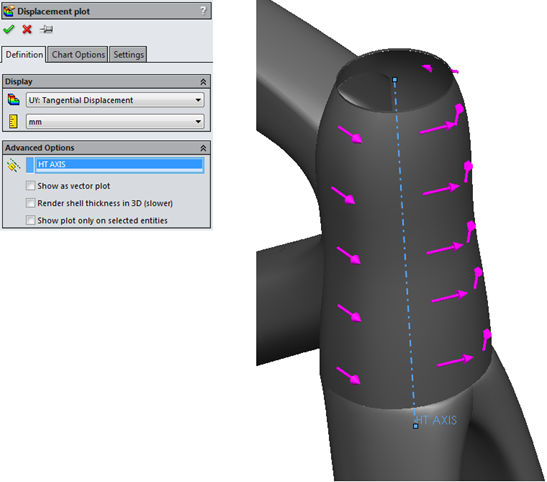
We can then calculate the stiffness by evaluating the angle of displacement (this is done by using the simple arc length formula: UY = rθ).
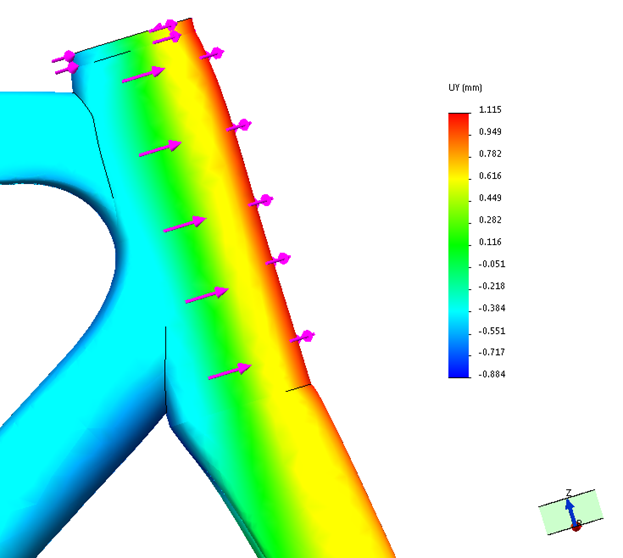
Circumferential Deflection: No Taper
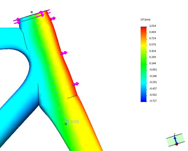
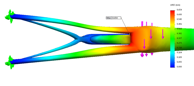
Circumferential Deflection: with 1 1/8 Taper
By calculating the resultant angle of deflection I was able to calculate a 21.5% increase in torsional stiffness!
It’s good to see some fact behind the hype.
Symmetric vs. Non-Symmetric Chain Stays
One limitation of the frame design is the component geometry (crank set, chain ring, cassette, etc). There is no use designing a frame that cannot fit standard components such as crank sets and derailleurs. However, the components only need to fit on the drive side of the frame, so the non-drive side can be ‘beefier’.
Symmetric Chain Stays
Non-Symmetric Chain Stays
By taking advantage of the extra space on the non-drive side, I was able to increase the lateral stiffness of the frame by 11%.
In the next part, I will further improve the performance of the frame design by using CFD (computational fluid dynamics) analysis to optimize for aerodynamic performance.
Thank you for reading, stay tuned for the next part!
Summary of results
| Design Aspect | Change In Stiffness (%) |
| Non-Circular Profile | 37 (Torsional) |
| Tapered Head Tube | 21.5 (Torsional) |
| Non-Symmetric Chain Stay | 11 (Lateral) |
| Seat Stay (+/- 1 mm thickness) | <<1 (Torsional/Lateral) |
| Top Tube Taper (1 1/10) | 3 (Torsional) |


