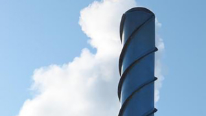
Have you ever driven by a factory building with a tall chimney? If you have, you probably also have seen spiral fins or ribs wrapping around the outside of the industrial chimney. There’s a practical reason for those fins.
Let’s get into it!
We’ll take a closer look at these chimneys using SOLIDWORKS Flow Simulation to see what purpose those spirals serve. We’ll use a transient analysis in SOLIDWORKS Flow to examine how air moves past a tall chimney over time: first without the fins, then with the fins.
Not only is this an experimental exercise, but also a valuable lesson on using (or not using) symmetry in a computational fluid dynamics (CFD) study of chimneys and similar cylindrical structures.
Modeling Airflow Around a Smooth Cylinder
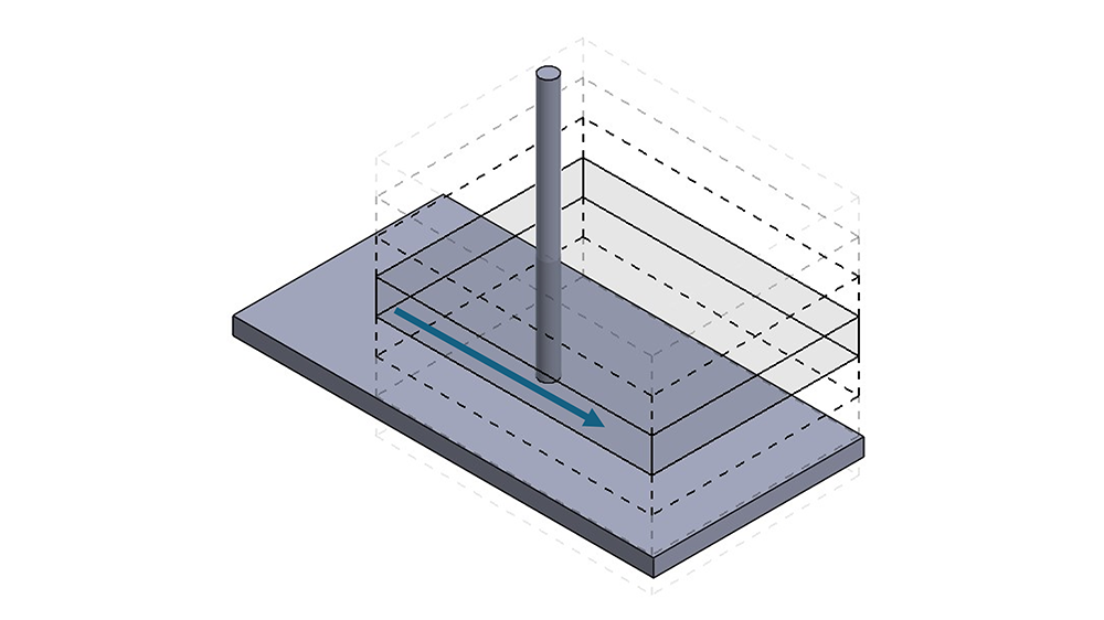
First, we create a smooth cylinder and subject it to a gentle breeze of 1 m/s. The simulation setup is relatively straightforward here: we use a transient external study.
The computational domain is simplified to a small slice of the cylinder in the axial direction, using periodicity conditions. This will allow us to examine the bulk of the flow effects away from the ends of the chimney in the middle section with less computational time.
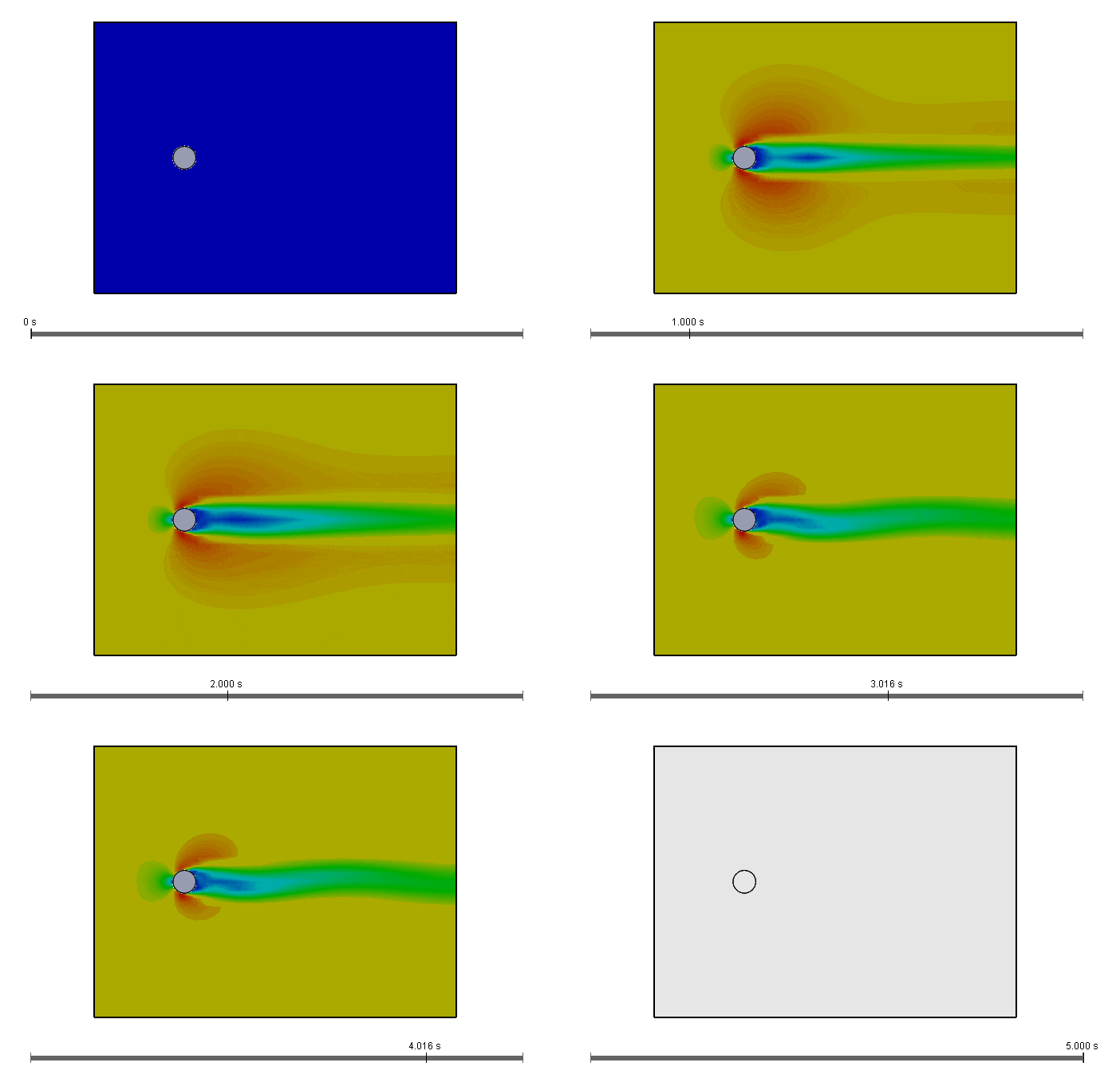
In the study setup, the velocity of the air was recorded at every iteration, so we can then view an animation over time of the airflow around the cylinder (our chimney).
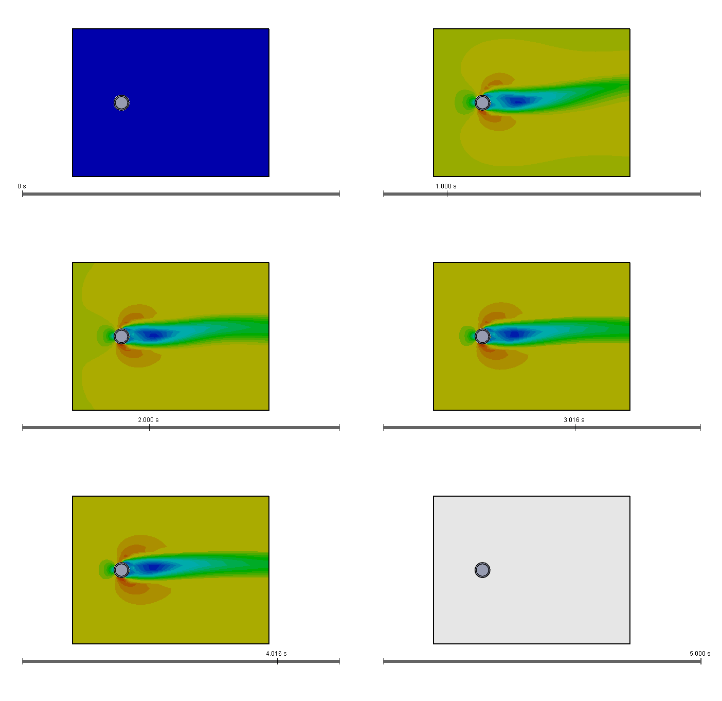
In Figure 2 below, we see the cylinder from the top, with air flowing from left to right. Blue areas represent lower air speeds, and red areas represent higher air speeds. Notice how the flow first builds until around 2.5 seconds, when an oscillation develops.
This oscillation is known as vortex shedding (or Kármán vortex street). It is often a concern in the design of chimneys, buildings, and older car antennas that stick up from the car rather than being integrated into the glass. Vortex shedding can typically occur on non-streamlined structures. The speed of the air (or fluid) that causes vortex shedding depends on the geometry of the structure, such as its shape or size.
The oscillating flow of air can cause the structure to sway, resonate, or even reach a dangerous loading condition.
How Spiral Fins or Helical Strakes Reduce Vortex Shedding
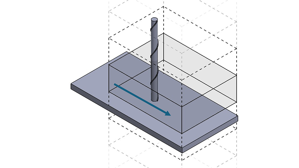
Next, we’ll explore the same airflow condition and test it on a cylinder with spiral fins around the outside. These spiral fins are called strakes.
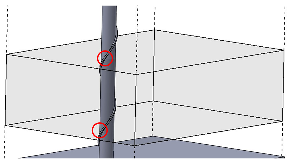
Because the strake follows a helical path around the tower, the computational domain is modified to the height of the strake pitch. This way, one complete rotation of the strake is captured, and the periodic boundary condition can still be used.
In the same top-down view from earlier (Figure 5 below), the oscillations around the tower are significantly reduced in intensity. The strakes disrupt the airflow and redirect some of it up and down, axially along the tower rather than allowing it to shed laterally.
In addition to reducing the amplitude of oscillation, the strake can also change the frequency of the remaining oscillations to a more favorable value, for instance, away from the natural resonant frequency of the structure.
Can Too Much Symmetry Hide Vortex Shedding?
Based on the results so far, we now know the strakes’ function. It reduces oscillation intensity.
But another lesson can be learned here.
What if the first simulation on the smooth cylinder had been done with another symmetry condition?
Perhaps, in a well-intentioned move to save time, we run the study on just half the cylinder, turning the circular cross section into a half circle. After all, the flow condition and geometry are symmetrical.
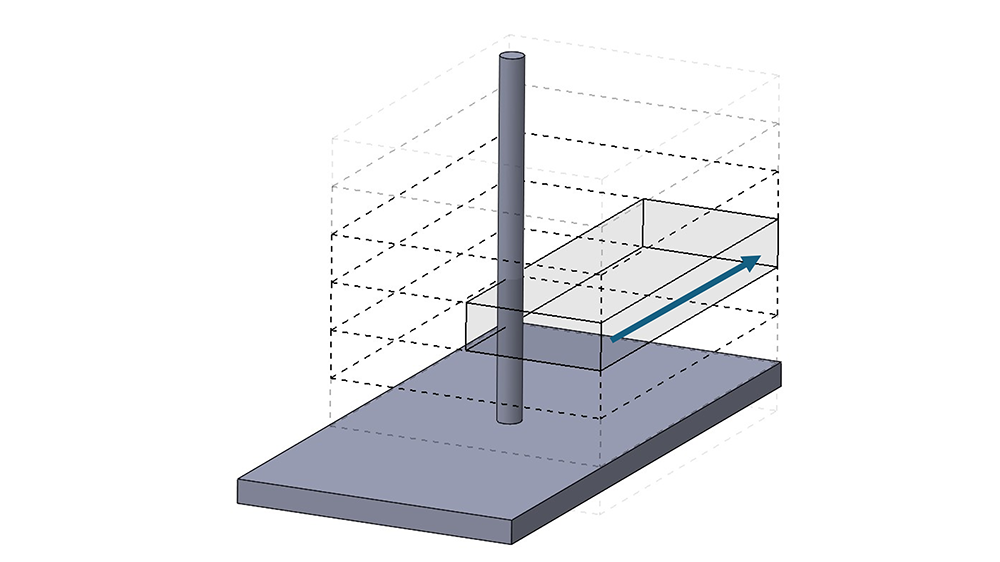
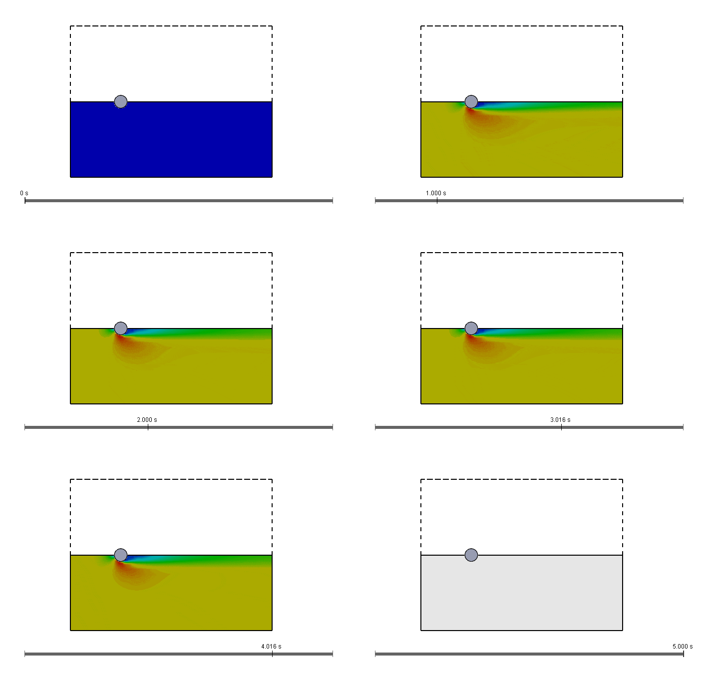
Once we run the study, the flow would look completely different. The symmetry condition prevents vortex shedding from starting, and the airflow is stable compared to the previous studies.
My Final Thoughts
To conclude, this article covers the natural phenomenon known as vortex shedding and explains why large industrial chimneys often have spiral fins around the outside, known as strakes. But it also sheds light on something we, as CFD analysts, should be aware of.
Even in some cases where boundary conditions, geometry, and flow conditions are all symmetrical, the flow itself is not guaranteed to be symmetrical. In these cases, using an improper symmetry condition on the computational domain can be a serious mistake and cause us to turn a blind eye to what may be a potentially serious resonance building in our structure.
If you have any questions about transient analysis, vortex shedding, symmetry conditions, or SOLIDWORKS Flow Simulation, we’re happy to help. Just reach out to us.