Vacuum forming tools are an application that is usually overlooked when exploring production tooling using additive manufacturing. If you are looking for a quick tool to pull just a few prototypes, or if you are looking for short-run production tooling, this may be the application for you.
I have seen companies produce a printed prototype of the product they are developing using additive manufacturing and then create a blister pack by printing the vacuum form tool for the packaging of the product. This allows them to show the product as it would appear on the shelf; making a better presentation to a marketing group looking for new products.
These can also be used to produce packaging for short-run production whether it be for display or packaging or any other application of vacuum forming. I have even seen an application where the vacuum formed parts were used as inserts for fragile parts that need more support when shipping.
Why Use Additive Over Conventional Tooling?
Here are a few of the reasons that additive can be a great option over conventional tooling methods:
- Additive parts require no CNC programming compared to a machined tool.
- The additive machine will run lights out without an operator needed.
- Depending on the size of parts, multiple variations can be run at the same time, reducing turnaround time.
- Honeycombing the inside of the part to reduce weight and needed material is an option.
- There’s no need to drill vacuum ports individually.
These tools can easily be produced using 3D printers. We have developed a process to make post-processing powder removal easy by just following a few quick steps below.
Post-Processing Powder Removal Steps
Step One: Create your part using a CAD package such as SOLIDWORKS and save this file as an STL. Use your usual design practices as you would for any vacuum forming tool including draft angles and feature details.
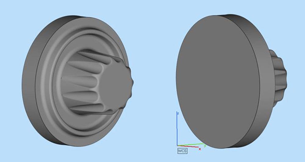
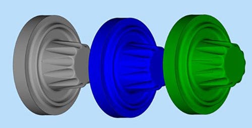
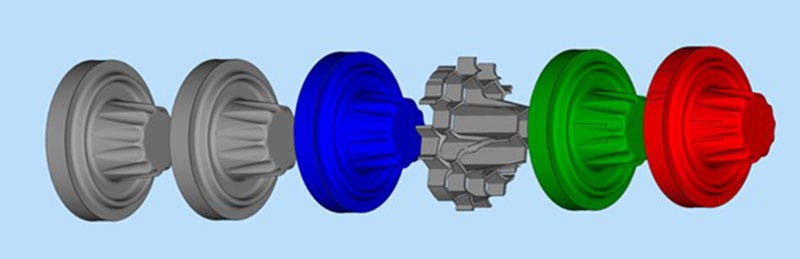
Original Solid
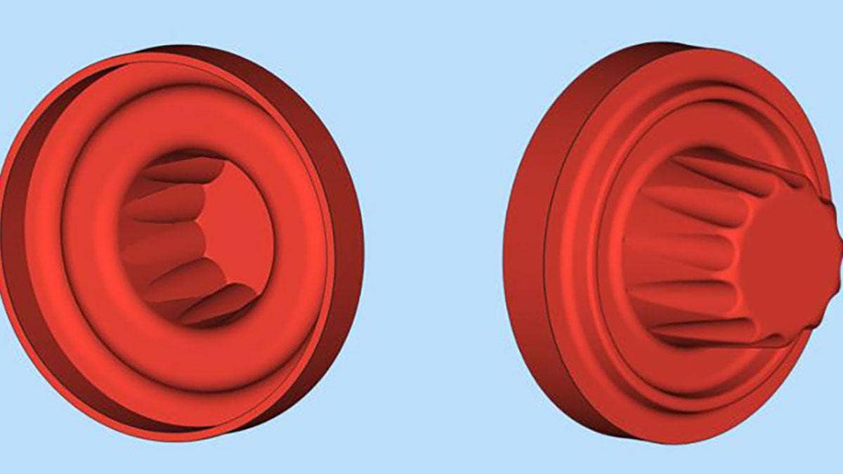
Step Two: After saving the original solid part, create a shelled out version “Shell One” by shelling the part in SOLIDWORKS. Wall thickness depends on the strength of part needed, I used .080”. Save this as an STL.
Shell One
Step Three: From the original solid file create “Shell Two” by shelling the original part again in CAD with a shell that is .001” thicker than the Shell One part. Example: Shell 1 = 0.080” Shell 2 = 0.081.”
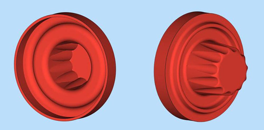
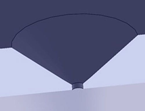
Step Four: Place your vacuum hole locations on the inside of Shell Two using the countersink hole technique in SOLIDWORKS. Position them as they would be placed when designing your vacuum forming tool to get the draw required for the part to be formed. Save the file as an STL.
Note: Make your small diameter hole on the outside of the part as small as possible but still allowing the powder to be cleared from the hole. I used a 0.020” diameter hole. Make the shaft of the hole as short as possible I used a 0.010” length. The countersink outer diameter needs to be larger than the walls of the honeycomb structure created in the next steps. This allows the powder, when bead blasted, to be cleared out of the holes around the honeycomb wall that may block the holes.
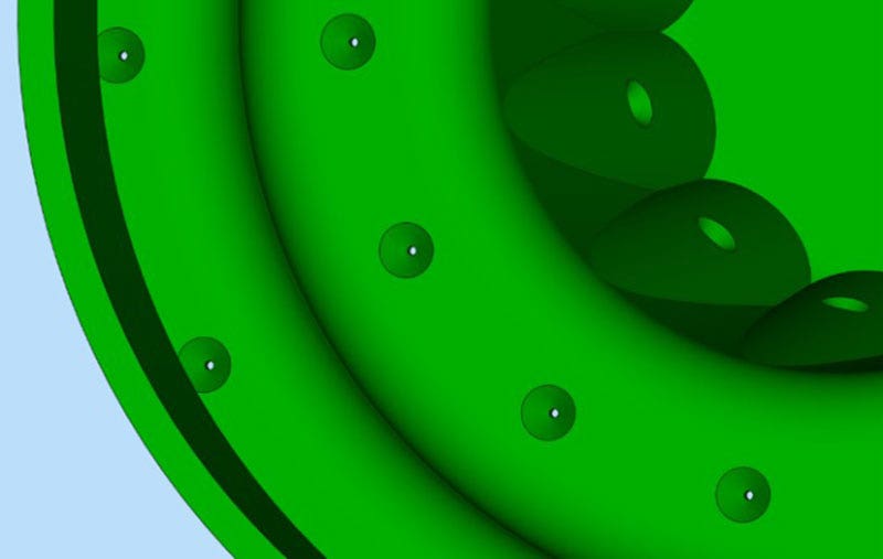
Shell Two With Holes.
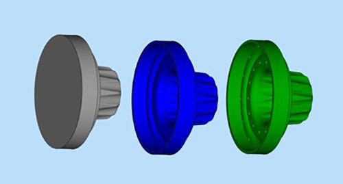
(These image shows them separated for display purposes only)
The Final Steps
Bring all three files into Materialize Magics software. They should come into the software located on top of each other.
Follow these simple steps:
Step One: Select the solid part by checking the box in the parts window.
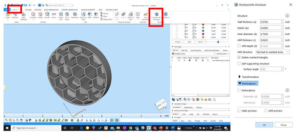
Step Two: Honeycomb the original part using the Materialize Magics honeycomb feature. I use the settings in the screenshot below. This can be adjusted depending on the strength of the structure needed and ease of powder removal in post-processing. Experiment with the settings to get the best strength and minimal material you can.
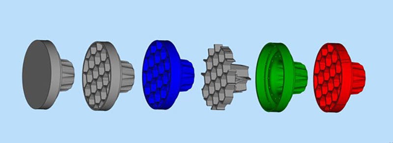
Step Three: Check the boxes selecting the solid part that has now been honeycombed and the “Shell One” part. Leave the “Shell Two” part with holes unchecked. Subtract “Shell One” from the honeycomb part.
Step Four: This will leave you with the honeycomb structure alone.
Step Five: Select the honeycomb part and the “Shell Two” with holes.
Step Six: Merge these parts together. Because Shell Two was created thicker by 0.001”, it will merge with the honeycomb structure. This will create a honeycombed part with the vacuum holes in the surface. Save this file as an STL or a 3MF file and import it for printing.
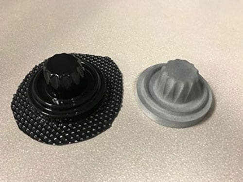
Final Pulled Part
To achieve a smooth part for better forming of thin sheets or clear materials, the parts can then be post-processed after bead blasting powder removal by sanding, vibratory finishing or vapor smoothing. Be careful not to allow the vacuum holes to close off.
Once the parts are designed in SOLIDWORKS, the process in Materialize Magics can take as little as less than a minute. This technique can also be produced completely in SOLIDWORKS if you do not have Materialize Magics available, but I find using Materialize Magics combined with SOLIDWORKS makes for a quick workflow.
Thanks for checking out this workflow. If you have any questions, don’t hesitate to contact us at Hawk Ridge Systems today.