For the new Simulation user (and even for the experienced user) meshing an assembly model can be a
real headache. Real-life assemblies, are complex, have detailed areas, and
often have thin or small parts that need to be incorporated in the mesh. While
SolidWorks has one of the most robust meshers I’ve ever had the pleasure of
working with, the act of converting your geometry to mesh can still be a
challenge.
To try to ease this pain, SolidWorks have introduced a couple of new tools and
workflows in SolidWorks 2011 to further improve the ease and speed of meshing.
First, and simplest, you will now see a new default meshing scheme when you
launch a SolidWorks 2011 Simulationstudy. It’s the curvature-based mesher, and
while it has been around since the 2008 release, its capability is greatly
enhanced in the new version (and you can still set the standard mesher back to
be the default if you wish, via the Simulation Options menu).
The curvature-based mesher interrogates the radius of curvature of each area
of the model, and tries to map mesh elements to it based on that curvature –
for example, small holes get tighter mesh elements than flat, thick plates. In
stress analysis, sharp corners generally relate to high stress concentrations
if they are in the load path. Because of this, tighter mesh generation in
these regions normally means more accurate stress results, so the
curvature-based mesher gives us some help with accuracy here.

For a given model, the curvature-based mesher will probably create more mesh
elements (and therefore take longer to solve) than the standard mesher, but
will generally mesh more complex models out of the box, compared to the
standard mesher. The other significant advantage of the curvature based mesh
is that it lends itself exceptionally well to multi-core meshing. Until this
year’s release, meshing was a single-core only process, so if you had a
quad-core processor on your system, SolidWorks was unable to use more than one
at a time. Both the meshing routines in SolidWorks 2011 use multi-core
processing to some degree, but the curvature based mesher has a computational
routine that performs much better in a multi-processor or multi-core
environment, particularly in assemblies with multiple parts using incompatible
meshing.
I thought I’d do my own, highly unscientific benchmark comparing the two mesh
regimes with a model that has given me some trouble lately.
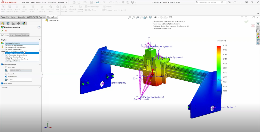
The model pictured has some small, thin display brackets that present a real
problem with meshing. Use of a mesh control with fairly small element size is
required to get a valid mesh.

To do this benchmark, I’ve used the default global mesh size, and the largest
mesh control I could to ensure the brackets still mesh – a 7mm mesh element.
This model is a great example of a situation with both large, broad items, and
small, detailed ones.
The results of the two different mesh types are below:

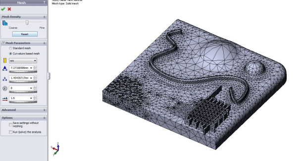
Below is the mesh generated by the standard mesher:

Below is the mesh generated by the curvature-based mesher.

In summary, the curvature-based mesher is significantly faster on this model,
but generates about 30% more elements. Overall, considering mesh+solve time,
curvature-based is slightly faster. In this instance, I wouldn’t feel
comfortable using the mesh density shown above in either case for accurate
results, and would want to refine further, but this serves as a useful
comparison between the speed of the two meshers.
For my day-to-day work, I’ve set the curvature-based mesher as the default,
but often run into models that get me closer to a complete mesh with the
standard mesher. My general procedure is to try a model with the curvature
mesher, if it fails, I’ll try it with the standard mesher. From there, I’ll
refine whichever one got me closest to a complete mesh. Of course, once the
model is complete, I’ll need to review the validity of the mesh for capturing
the stress in the model, and possibly refine from there, but that’s a blog for
another day.
Stay tuned as my next post will be on the new meshing workflow for failed mesh
parts in SolidWorks 2011.