Sometimes there is no way to fully scan a part that has features hidden from sight. Since optical scanners are analogous to spray-painting with light, you must have line of sight on any feature that you want to “paint.” In many of these cases, the only viable option will be to use an industrial CT scanner. The cost and facilities requirements of CT scanners can be prohibitive for most companies, however, and outsourcing to a CT service provider might delay a project or pose IP issues that take time to resolve.
Some parts are too expensive to sacrifice or flatly irreplaceable, and leave us no option other than CT scanning. But many cases can be resolved by sacrificing a part, usually by cutting it into several pieces. This is especially practical in cases where parts are easily obtainable and replaceable. A similar, but non-destructive method of disassembling parts is detailed in our alternate post, “How to Master Assembly Scanning.”
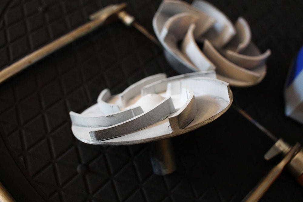
Scanning An Enclosed Impeller
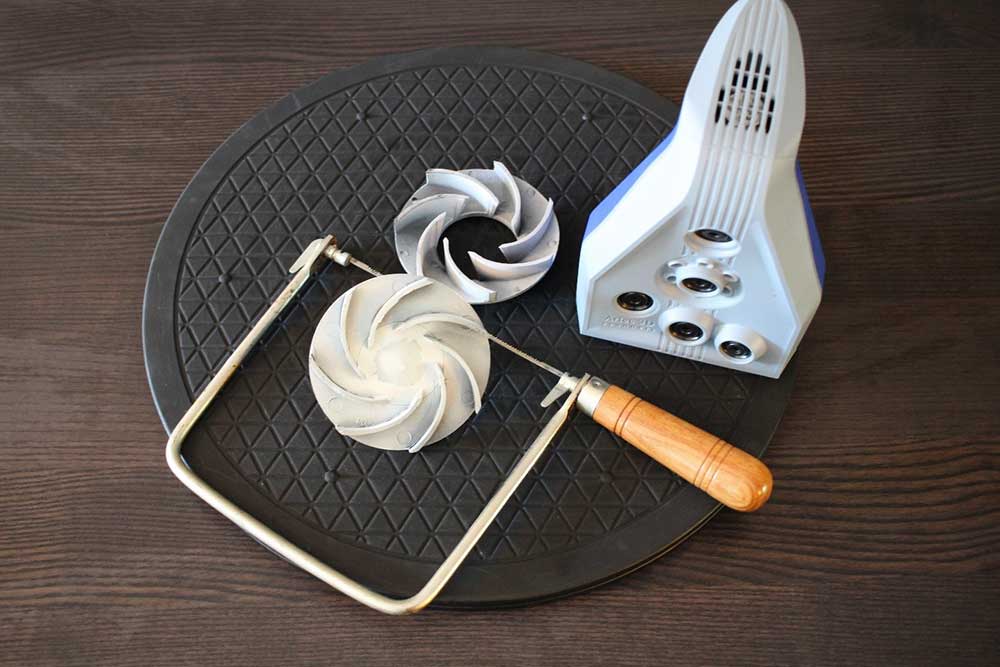
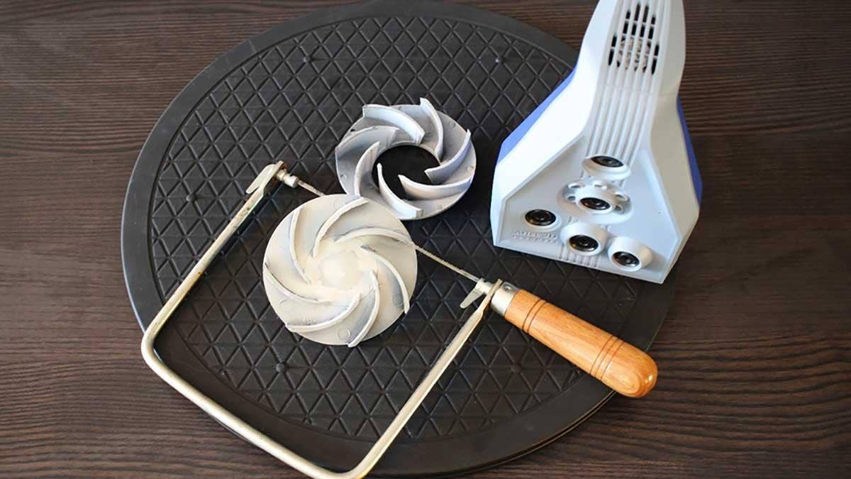
An enclosed impeller, cut in half with a standard coping saw (shown with the Artec Space Spider).
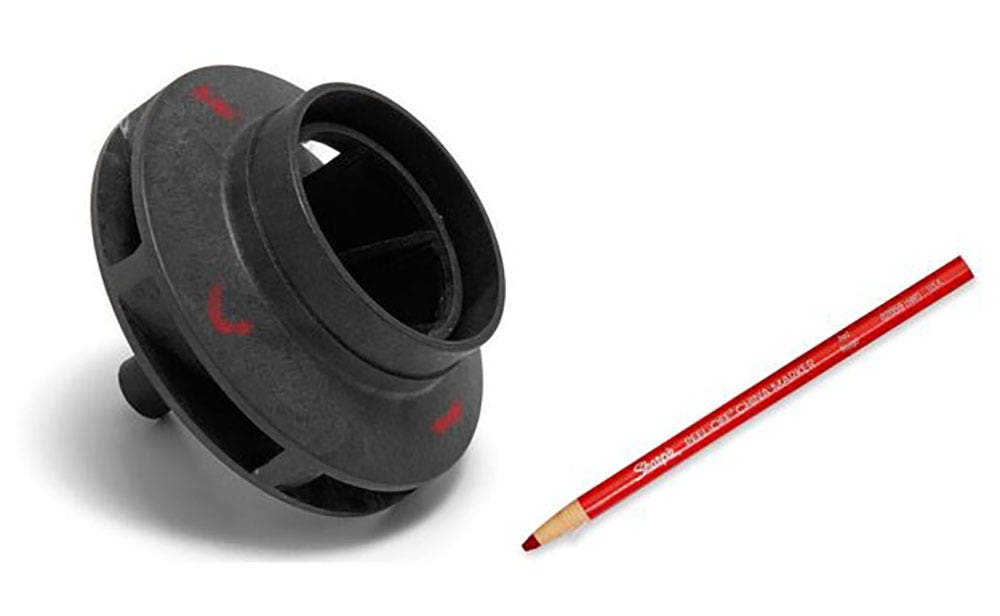
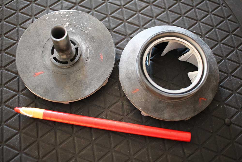
We’ll begin by scanning the impeller as-is. Before we start, we’ll make some marks on the part for later visual reference. Since this part is symmetrical and one section looks the same as another, three or four marks on each main face will serve as visual reference points and ensure that we are able to tell one side from another when we want to align our scans later on. To that end, it’s important that these marks be easily distinguishable, so they should be made with different angles, lengths, shapes, or colors.
 `
`
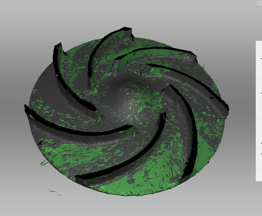
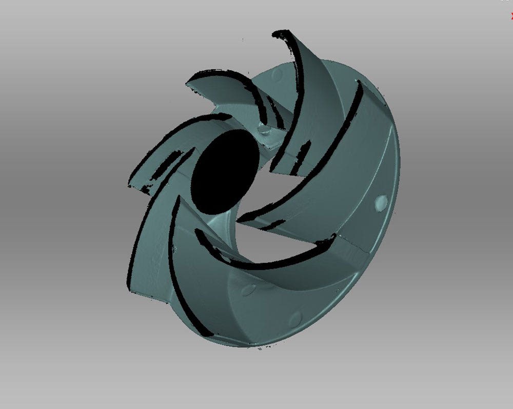
In the cut-away view below, we see that the outer areas were easily captured, but some of the important inner areas were hidden from sight and were not captured well. Bear in mind that this part will be remodeled by revolve-patterning a single blade, so it is not necessary to capture every blade completely.
Since this object is dark in color, some talc spray or disappearing spray may allow us to pick up some of these hard-to-capture areas. Before we resort to sacrificing a part, we’ve sprayed some talc into the recessed in hopes of getting a better scan. While the talc helped, some areas remained completely hidden from line of sight and were not possible to capture.
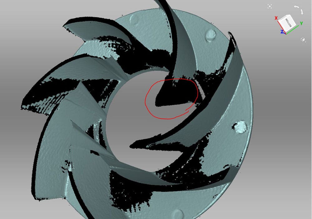
An incomplete scan of the intact part show with a cutaway view.
Most importantly, the suction side of the leading edge was obscured from sight. If you work with impellers, you already know the critical importance of the leading edge. This area will greatly affect how fast it wears and how well it performs with various liquids at various temperatures. The leading edge is typically optimized for several important variables so it is critical that it be reconstructed faithful to the original profile. At this point, we’ve established that we can’t fully remodel this part with traditional optical scanning alone.
Cutting the Impeller
We don’t have access to a CT scanner, but we can easily obtain more of these impellers are a reasonable cost, so we’ll proceed with sacrificing one. In this case it will mean cutting the impeller in half with an ordinary coping saw in order to expose the full cross section. After taking about two minutes to saw through the part, we knock off the burrs with some sandpaper and add a little more talc spray for good measure. While the part is already perfectly scannable without talc, the lighter color and greater opacity will produce better quality data with less noise and it will also increase the capture speed.
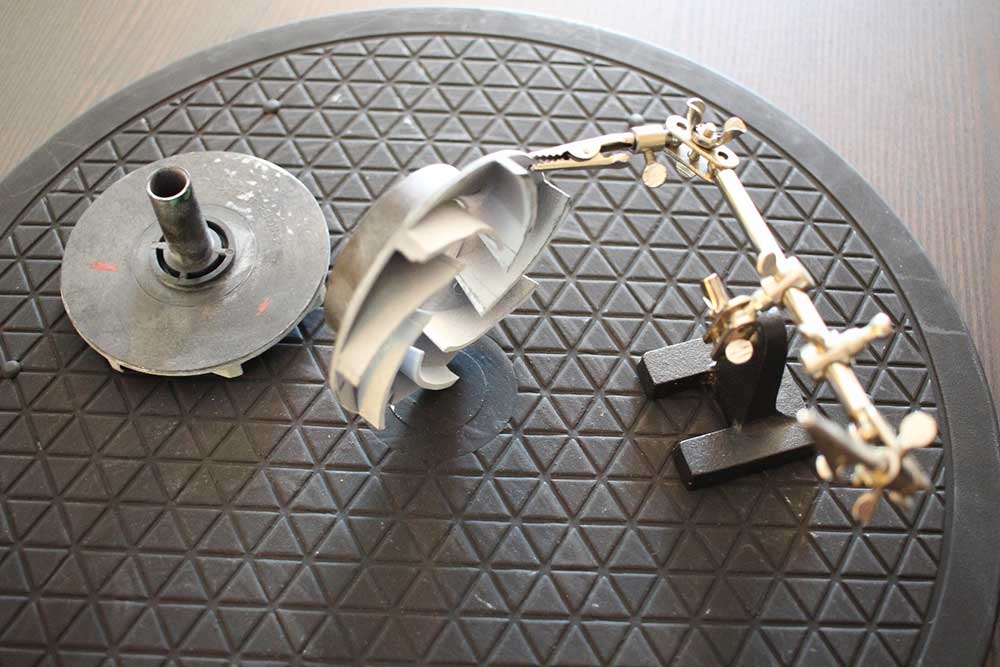
In order to use our red markings as a visual cue for proper alignment, we’ll need to capture both sides of the part in a single scan, so we’ll use an object to hold the part upright so that we can scan both sides without repositioning the part. In this case, we’re using an articulated clamping device commonly used in hobbies like fly tying, but an ordinary C-clamp or a piece of clay would work as well.
After scanning each individual half, we’ll need to align them to the intact version we scanned beforehand. These new surfaces created by the cut were not present in the original scan of the intact impeller, however, so there is no equivalent geometry in the original scan and therefore it may confuse the alignment algorithm, resulting in an imperfect alignment. To avoid that possibility, we’ll go into eraser mode first and erase the freshly cut surfaces from the scan before we attempt to align them.
The new surfaces created by the cuts have been erased so as not to confuse the alignment algorithm.
Now we can align the two groups using the marks we made beforehand.
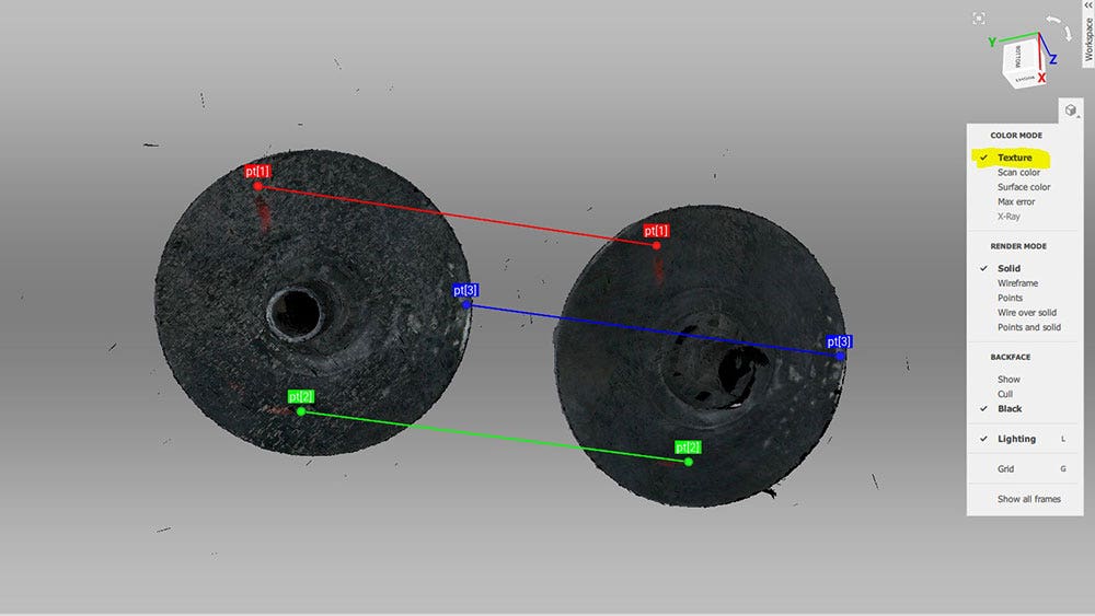
Manual alignment in Texture view using color grease-pencil marks to guide point placement.
Completing the Scan
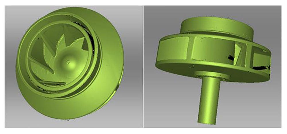
Once both cut halves are aligned to the initial intact scan, we’re ready to run a Global registration on all the scans at once. Then we can run Outlier Removal and create a Fusion at our desired resolution. As the pictures below demonstrate, the sacrifice of this object has resulted in a much more complete scan, and the cutaway view shows that both sides of the leading edge are well defined. While there are still some minuscule areas of missing data where we erased the cut surfaces, they won’t impede the duplication process and we now have plenty of data to accurately reverse-engineer this impeller.
Check out our website to learn more about Artec 3D scanning products and their functionality. If you have any questions, contact us at Hawk Ridge Systems today and we will be happy to help. Thanks for reading!


