Have you ever wanted to securely embed hardware and components inside your 3D printed parts? In some of our previous content, We’ve touched on how Markforged composite 3D printers allow users to pause their prints in progress in our previous blog, “6 Threading Options for Your Markforged 3D Printed Parts.” In today’s blog, we’ll be taking a deeper dive into this functionality and how you can use it to enhance your 3D prints!
How It Works
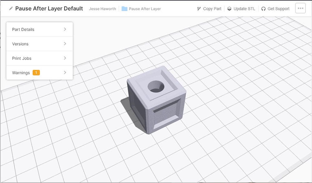
As is the case with 3D printing in general, enabling a pause on Markforged systems starts on the software side. Once you have uploaded and sliced a part with the Markforged Eiger software, each discrete layer will be visible via the Internal View.
Within this view, all you need to do is find the layer where you would like your automated pause to occur. When you have navigated to that layer, enabling the pause function is as easy as toggling the Pause After Layer command and saving those changes.
An automated pause only takes a few seconds to set up.
When you print a part that contains a pause, the printer will automatically stop printing after that layer is complete. With a connected printer, you are then notified via email that the pause occurred. On the printer side of things, you can either resume or stop the print job completely via the on-screen UI. If the print is resumed, it will complete as normal!
Once the printer has paused, the job can be resumed or stopped with the touch of a button.
Embedding Threaded Components
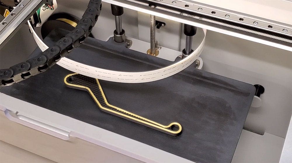
While pausing a print is easy, deciding how to utilize this functionality can involve a bit more thought. By far the most common use for this function is embedding threaded features into parts. In our example piece illustrated below, we have a cavity that was designed for a specific nut size.
An example piece with an internal cavity designed for a nut.
Once we have oriented and sliced this part in Eiger, we can navigate to the top layer of our component cavity and insert a pause, just like we did with the brake lever.
Inserting a pause into our example piece.
On the printer side, the pause allows us to insert our component. Before resuming the job, all we need to do is confirm that the hardware does not extrude above the current layer of our part. A component that runs above the current layer presents the risk of print head impact and job failure.
A quick visual verification is recommended before resuming a pause with an inserted component.
Once we have verified that all looks good, we can resume the job with the UI, and the printer will start to overprint our hardware! When the job is complete, it is as easy as removing the example piece like we would any other Markforged part.
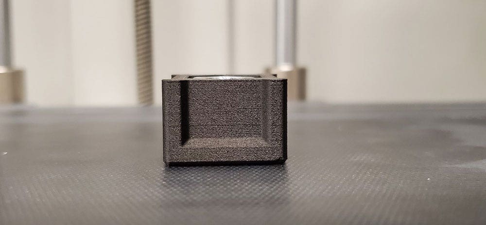
An example of a captive component print in progress. The right-hand example shows the component, while the full version on the left shows it being overprinted.
A full version of our captive example on the left, with a partial version on the right to show the internals.
Strange Shapes
So far we’ve covered how the Pause After Layer functionality works, and how it can be used to embed hardware with straight forward orientations. What about hardware with uneven top surfaces or strange orientations? To show how that can work, we’ll flip the print orientation of our example piece while keeping the intention of embedding a nut into the cavity. The following illustrations show a cut version of our example piece so that the cavity can be seen.
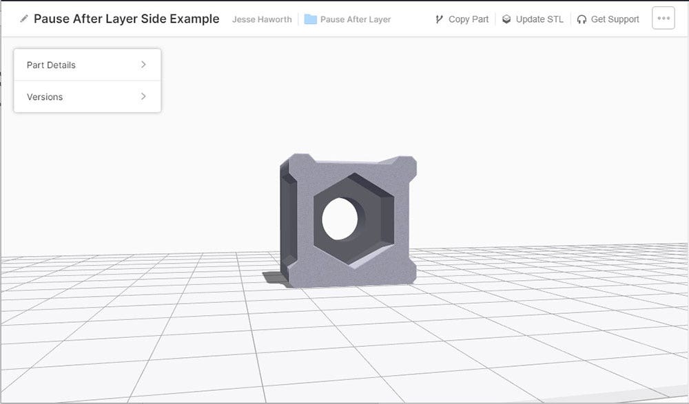
Our example piece flipped onto its side in Eiger. The grid represents the print bed.
This orientation presents a bit of an issue. If we wait until the top layer of this cavity is done printing, we will be unable to fit our component into the cavity itself.
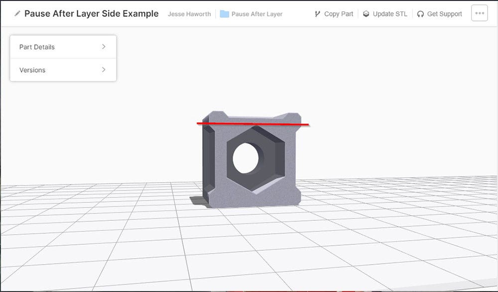
If a pause is set at the top layer of the cavity, we would be unable to fit the component.
If we place the component in our part during a layer that allows us to do so, however, the print head will certainly impact the insert. An option is to extend the cavity up to the top dimension of our nut, but this leaves a void in our part that may allow the nut to move, while also presenting an issue of having the top layers print poorly due to no supporting geometry.
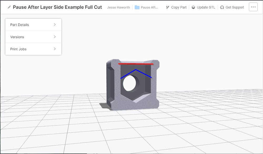
A version of our example with the cavity extended above the dimensions of our component. The space above our component (blue) will not support the layers after our pause (red).
To account for these concerns, the simplest solution is to print a small insert that will be placed into our part along with the actual component. This insert results in a planar surface across the entire paused layer, which gives the material support for subsequent layers. It also keeps our internal components in place!
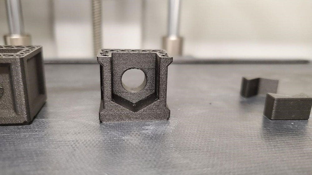
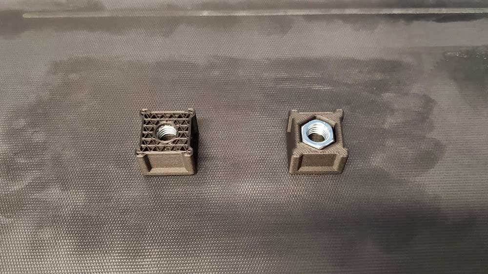
Our two flipped example pieces being printed. The two inserts on the right will allow layers following the pause to be upheld.
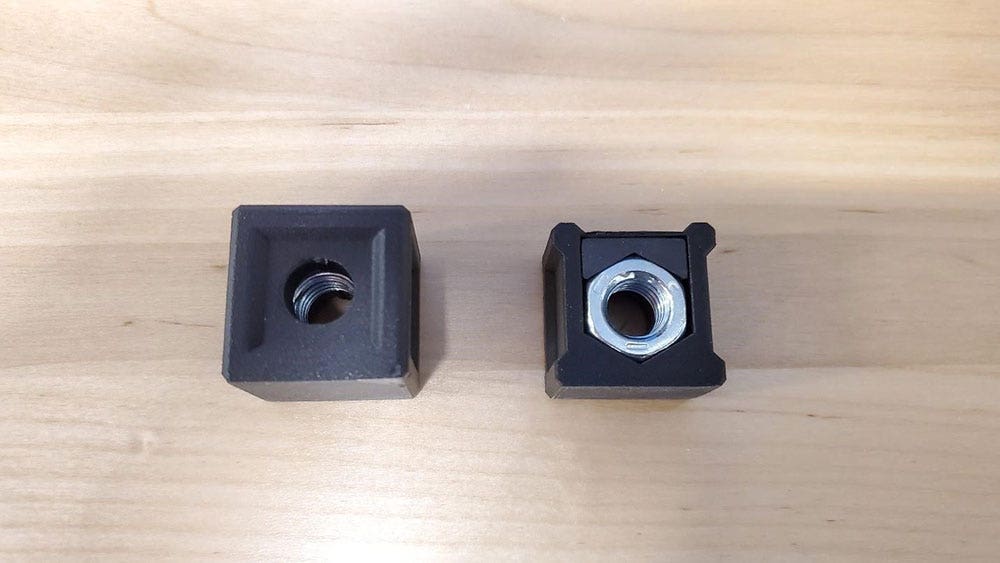
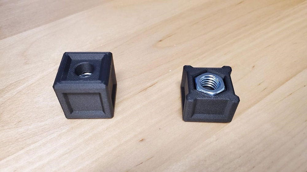
The two finalized pieces. Our cut example on the right shows what the full version would look like internally.
This approach allows us to insert all sorts of hardware, even if uncommon geometry is present. If we had wanted a bit of extra grip between our hardware and printed insert combination, we could have used an adhesive to bond the printed insert to our component or bond the top layer to our insert. Loctite 401 is an excellent candidate for creating an extremely rigid bond and could be useful where the placement of internal components is key.
Enhancing Your 3D Prints
The pausing functionality of Markforged 3D printers opens the door to many options besides nuts. Maybe instead of a threaded feature, you could embed a magnet into your part for mounting purposes? How about creating a pause so that electronics or hard to route wiring could be placed? Perhaps piping that allows liquid with extreme properties or temperatures to flow? With some of the techniques mentioned here, the possibilities are endless.
Have an idea for what you’d like to place inside a 3D printed Markforged part? Let us know in the comments. Thanks for reading everyone! For more information or if you have any questions, be sure to contact us at Hawk Ridge Systems today.