If you have a need to analyze electronic products for thermal requirements, SOLIDWORKS Flow Simulation offers the most seamless way to get accurate results in less time. How can you ensure those results are based on accurate real-world data? Take a look at how Hawk Ridge Systems’ own analysis consulting engineers use the Electronics Cooling add-on module to input component and board properties directly from common datasheets or other software. This reduces guesswork while increasing accuracy.
Analyze Electronic Products for Thermal Requirements
Video Transcript
Introduction
Welcome to the webinar Wednesday presentation of From Datasheets to Results, which is thermal analysis with the SOLIDWORKS Flow Simulation Electronics Cooling Module. I’m Damon Tordini. I’m the product manager for Flow Simulation. I’ll be going through one of the most popular applications for this product which is performing analysis on some sort of electronics product to check temperature constraints.
We will be focusing on something that we don’t talk about a lot, which is when you’re getting to the point where you’re planning on doing the setup for one of these things, what capabilities there are in the software that let you actually take whatever the real world data is about the product that you might be will find, and how you actually can put that into the software and make sure that the results you’re getting out are accurate. I’m sure like many of you out there, the typical SOLIDWORKS user among our customer base is mostly going to have a mechanical design background. That’s what my design work background was. Throughout the years, I’ve managed to learn a little bit about circuit boards and components that may go on them. But in many cases, if you’re like me, you found yourself in a situation where a product that you might be designing or validating needs to be cooled. But in a lot of cases, a big part of that cooling is going to be something that was already designed into the board itself or maybe even inside the components. And while we might be trying to look at some mechanical design of changes, such as moving fans around, putting vent in an enclosure, or designing a heat-sink – in a lot of cases, whether or not the chip can stay at a proper temperature is also dependent on how that internals were designed or other aspects of let’s say the layers and PCB or cooling devices that we might use that are more sophisticated.
So if we want to make sure that we are checking these thermal requirements, and we’re getting the best mechanical design, we want to make sure that we are capturing those electrical design features as accurately as possible so that we know if, for example, the chip itself has been designed in a certain way to get the heat out or we’re accounting for that too. In addition to whatever kind of heat-sink we might be trying to create, or how we decide to create the vents or component placement on the circuit board. We’re going to look at how you could use solid works to have an integrated or what we call design validation process where you can take some of that information from the suppliers of these components and put it into SOLIDWORKS to increase the accuracy of your results. So of course, uh, in the solution portfolio at orca systems right now we’re talking about the simulation family of products. And of course, those are highly integrated with the design tools, which generally are going to be SOLIDWORKS. And so, let’s think of a case study where we might be using some of these tools.
Compact Personal Computer (PC)
In this case of a compact PC, a compact personal computer where we got really just one mainboard with some components on it. In order to kind of simplify things, we’ve got a single exhaust fan on this case, just trying to get the heat out. And we’re cooling those things via heat pipes. And I think we’ve got a thermoelectric cooler in there, and of course, the chips themselves have been selected for their cooling.
So we’re going to try to see what changes we might make to the layout of the board to figure out if those components are going to be below their thermal constraint, which in this case, we’re going to say, 70 degrees – in order to make sure that the mechanical design changes we want to try will give us a good conclusion.
We need to make sure that we’re capturing how that chips are going to behave accurately. The way we can test these things with a product called SOLIDWORKS Flow Simulation. That is in the SOLIDWORKS simulation family of tools, meaning it’s going to run directly inside SOLIDWORKS of your existing solid models. So of course, there’s no you need to export the model or create the conversions of it, it uses the existing solid geometry.
General Purpose Fluid Flow & Heat Transfer Simulation Tool
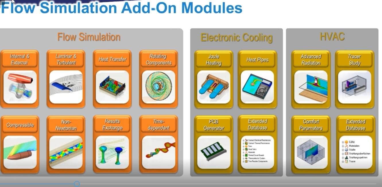
And specifically, this is what we call a general purpose fluid flow and heat transfer simulation tool. Which means it can be used for a lot of different purposes, but the most common one is electronics cooling, as we’re going to be looking at here. One of the best parts about this product is that because it runs directly on the SOLIDWORKS model and because the mashing technology is very automated and very robust.
In most cases, you’re going to be able to take the exact geometry that you’ve already got, whether that’s something you created, or if it’s got some circuit boards in it, that were maybe given to you and you won’t have to modify them in any way before you write your analysis. And once you set up the analysis, you’ll be able to start playing around the design trying out different changes to see what happens much more rapidly than if you had to sort of outsourcing it or create special variations of the design just to do CFD.
Electro-Mechanical Products
This is something that any SOLIDWORKS design engineer would be able to take off. Now, of course, if you are designing an electro-mechanical product, you’re going to have a circuit board in it. And in many cases, you might be using a newer product that came on the market a couple years ago called SOLIDWORKS PCB, which is a circuit board layout tool based on outcome designer. And if you choose to use this tool or something like it, you’ll either be collaborating your board layout directly into the SOLIDWORKS 3D model, or you might be importing some other kind of board file like an IDF through the circuit works. The reason this is important is that in different board layout programs, you might be exporting different levels of detail in the geometry to SOLIDWORKS.
There are certain programs out there that would let you export the entire internal design and details of a board, for example. And maybe even fully detailed internal components on the board. But from our experience, that’s pretty rare.
In most cases, you’re probably going to get something a lot more simplified. For example, just a solid block to represent the PCB. You would probably also get solid components, where each chip, for example, is just maybe an extruded, or a couple other simple features. And that’s fine because it does help speed up this integrated design process where you could go back and forth between mechanical design and SOLIDWORKS and your board layout.
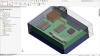
But what that means is, if you are bringing in a PCB, really with any of these methods, you probably are going to have a somewhat simplified model of the electrical side. Because again, that’s not something that you would create from scratch in SOLIDWORKS. And so we need a way to represent what those internal details are, just like you’re seeing in those board layout images there in SOLIDWORKS.
Probably, in most cases, you’re not going to be modeling the internals of a chip or modeling in the solder balls. But we need a way to account for that stuff. Something that is probably a little more typical for what you see, will be like in the bottom right image there. Once I bring this board into SOLIDWORKS, which of course you can see the fully detailed version of on the left. For example, those ram components and the memory chips on the right-hand side of the board, they just become simple blocks.
Again, every company is different. But, this is what we usually see. How do we account for those details when we’ve already simplified the model in SOLIDWORKS? Well, the key to this is that SOLIDWORKS Flow Simulation has a special add-on module and there’s actually two of them. And one of them’s called the electronics cooling add-on module.
And that has some capabilities, specifically, for defining the properties of these types of components to make sure that they’re being accurately represented from a thermal standpoint when you’re going through the analysis. And that way we won’t have to spend as much time importing all the internal mechanical details of a component, which we may not even be able to get in some cases. So we’ll be going through some of those features in a moment here. First of all, let me pop up the model and show you what this kind of case study example is gonna look like. And then we’ll go through and look at what the electronics cooling module adds, and how we actually could get those properties in there from real-world data.
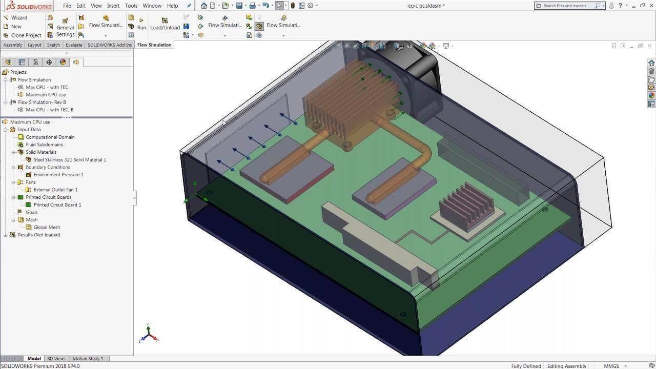
Let’s open up SOLIDWORKS. And this is just going to be a normal SOLIDWORKS assembly of course. I’ll open it up here. So again, we’ve got sort of a sheet metal enclosure, we’ve got a-a single large circuit board with the CPU and memory controller on there, and we have some heat pipes connecting those chips to a big heat sink right in front of this exhaust fan.
Analyze Temperature
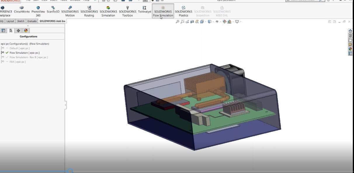
If we want to analyze what the temperature is in some of those chips would be, we can turn on the flow simulation add-in here by clicking the button from the command manager, and then we would need to create a new simulation. Now, the flow simulation add-in starts with the wizard interface. So even if you’ve never really done this before, most of the time, you’ll be able to remember pretty quickly how to do it by following the steps in the wizard.
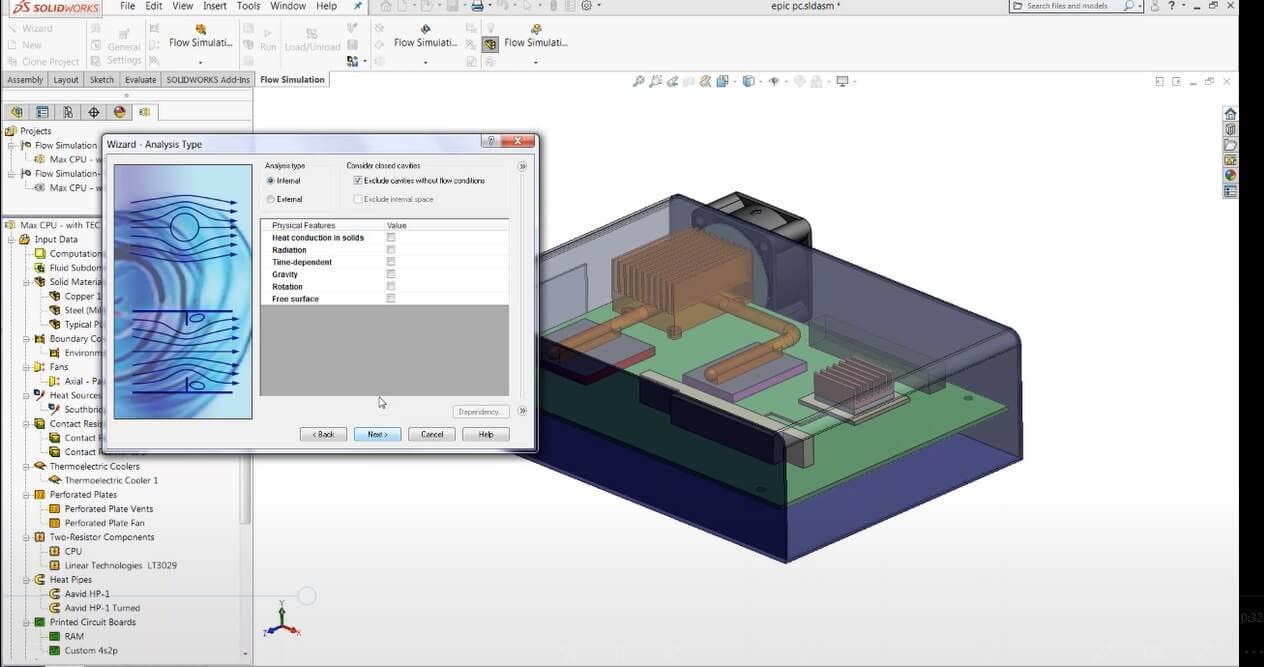
Just to give you an idea, we’ll go ahead and create a new project right here. I open up the wizard and the first thing I do is give it a name like maximum CPU use. I would then select whatever configuration of the model I want. In some cases, you might have a fully detailed version of this assembly with all the internal details. But you might also have a simplified version where, again, the components are represented as simple extrudes, or other single bodies which is what we usually see.
So we’ll give it a name and make sure we’re on the right version of the model. We can throw in our units, for example, SI units, and maybe Celsius for temperature. Then we can choose what physical features we want to include and what actual physical effects are accounted for in the simulation. For example, if we are looking for temperatures inside solid components, of course, that means we need to account for heat conduction, so we’ll check the box next to that.
If the effective air rising on natural convection was important, we would turn on the gravity check-box. Although, in this case, I’ve got a big fan on there that’s pulling the air, so that’s probably not as important. And of course, there are other things I could turn on to like radiative heat transfer. Let’s say, really hot or maybe outside the sunlight. I could even do a time-dependent simulation to see how long it actually takes to heat up or how long it takes to cool down once I have turned off the device.
Fluids Library
We got a fluids library here. Of course, most of the time, we’re going to be specifying air in a product like this. In some cases, you might have a water cooling setup, in which case, you could also add water to the analysis and define a separate fluid space inside the water line or inside the pump. You’ll notice we do have heat pipes in this model here, but we’re not going to need to simulate the internal fluids or face the change of the heat pipe, because of the ability to just bring in the heat spike-heat pipe specifications from the supplier.
So we don’t need to simulate those complex physics. We also put in our default solid material. We’ll go ahead and just choose an insulator material here, which is going to have zero upon activity. Then we’ll specify the other materials later, like copper. We can put in some wall conditions, we’re going to assume smooth walls and no radiated heat transfer. And we’ll just use the default ambient conditions, sea level temperature and pressure.
Once that’s done, we’ll have a new project here. Then we can go and specify the rest of the detailed setup conditions. For example, our boundary conditions, which would be where the air is able to get in and out of the box. In this case, I’ve got a vent on the left side of the enclosure over there, and one on the bottom. And while those were in the original model with the actual detailed slot profile – here they’ve been simplified to a simple rectangular cut-out.
If we wanted to, there’s a way to specify what that whole pattern was so that the airflow is reduced accordingly. But it would be as simple as selecting that face, for example there, and specifying what we would call an environment pressure boundary condition. And that’s just gonna mean that the boundary condition will allow air to come in or leave the system based on any of other flow conditions we put in, such as the volume flow rate.
We also got a fan here, which is going to be removing the hot air from the system. And of course, we could put in another one of those boundary conditions, like for example, a fixed volume flow rate. But if you’re familiar with fans, you know that the flow rate you actually get from the fan is gonna depend on a lot of other factors, particularly, if there’s anything restricting the flow like that the heat sink I’ve got.
Curves
If I move that heat-sink around, or if I let’s remove some of the this, I would need to put in the actual fan curve. Now flow simulation has a library of some limited fun curves, and if I were to go here and create the fan condition simply select that face say it’s an outlet fan and then we need to browse and select the fan that I wanna use. And we’ve got some from last year. I can select one of these and you’ll see if I go into the actual engineering database itself, the data that’s contained in here is a curve that shows the relationship between the pressure drop across the fan or pressure rise and the volume flow rate. The bigger the pressure difference lower the volume flow rate.
Again, if I’ve already picked my fan and I’m trying to design other stuff like this heat-sink, this is a great choice. If you don’t know what fan you want yet, you don’t have to use this. You can just put in a flow rate and that might help you decide which fan model that you need to choose down the road. There are also some different solid materials, of course, we might put on. For example, some of these connectors we could assume are plastic, or maybe the case we want is steel, and that’s just a matter of selecting the components and specifying the material and click the cover there. I’ve got some predefined materials like for example stainless steel 321.
So, that’s all pretty straightforward. Now, if you didn’t have the fan curve already in the library that’s something that you could request from the vendor and again that’s probably on any page you get for the fan it’ll be a simple matter of typing in those properties just like I showed you a moment ago. It’s the same thing with solid materials about our thermal conductivity and probably a specific heat. But what about some of these other more sophisticated components on the board? That’s when things get a little trickier and we need to take advantage of the electronics cooling module capabilities to put in more accurate data.
CPU
I’ll give you an example of course. This CPU right here. If we were to split it up and look at some of the insides, we’d probably find that you know, there’s a silicon wafer in there. Actually, this one might be a BGS and there’s probably a plastic case on the side and maybe even a heat scrubber on the top. This is a little piece of aluminum to help get the heat out.
I’m going to pretend that the thermal resistance or thermal conductivity throughout the chip is the same in all directions and we can tell right away that that’s not again a very good assumption, right? We know that the heat is going to get out of that chip to the bottom of it where the board goes differently than to the top where this heat pipe is connected. So, how do we account for that or other factors like what the inside of this PCB looks like? Well, that’s where these capabilities and the electronics cooling module come in. The first one I’m going to look at is something called the PCB generator, PCB layer definition. If you have a circuit board, which of course is made up of alternating layers and dielectric and conducting material, and where you’ve got traces of ground plans and what not, all those internal features, of course, contribute to the heat transfer.
And like we said, in the beginning, more and more of these products get smaller. For example, the cell phone has the thinnest case on the planet. We need to account for some of those factors and make sure were simulating the heat transfer accurately, any cases that board itself is really the only thing getting the heat out of these components. So what the PCB generator does, is it allows you to take in the actual layer information from that board into the library of flow simulation.
And then it calculates the equivalent thermal properties for you, including how much thermal resistance there is through the board, which might be very high compared to how much resistance there is in the plain of the board, which may be much lower. We can put in the number of conducting layers in the board, for example, an eight-layer board. We can put in what the thermal coverage is. For example, a ground plain might be almost all copper, so it might be 80%, or you know a simple power trace might be 20%. We can put in the thicknesses of the layers, and specify what material they are – whether that’s copper or FR4 or something else if it was the dielectric.
PCB Generator
From all that, the PCB generator calculates the thermal properties. Now, where would we get this information? That’s, of course, one of the questions. Then you might be able to just call up the board layout team or maybe the company that did it for you and ask.
But if they aren’t sure, the best place to look would be in the actual board layout software that they were using. For example, if they were using SOLIDWORKS PCB, there is something called the Layer Stack Manager, which actually lists the same information as a cable that shows all the layers whether it’s the dielectric or the conducting material and what the thickness is.
That combined with looking at the top-down layout of where the traces are will help you input what these layers are and what the coverage is in each one. Other board layout programs are going to have the same type of information, whether that’s LTM designer or pads or any of the others. For example in our model here, I got a little custom over layer board that I could put in. And if I just go to the printed circuit board feature, I can go select it from my library which looks like this.
I’ve got all my material properties in there, and then the board definition itself. And when I put that info in, SOLIDWORKS does all the work, calculates the effective thermal conductivity in the different directions, and I all have to do is pick the part. So, no need to do a bunch of math on your own in an Excel spreadsheet. Now, if you wanted to account for more sophisticated circuit board features such as Vias underneath one of the chips, that is copper going all the way through the board, you could also split that part into a couple other bodies.
For example, a simple rectangular sketch underneath that chip, do a split feature, and then the board would be two solids. You could put copper on one of them to represent those Vias, and then the rest of the board would still be this, printed circuit board feature that we just looked at. Let’s look at another example, what about these chips themselves? These are obviously just modeled as a simple extrude feature, so I need a different way to put that information in.
Two-Resistor Component Model
That’s where another capability of the electronics cooling module comes in called the two-resistor component model. The two-resistor component model is what we call a one-dimensional network assembly or network relay, which was created and improved by the JEDEC standard to more accurately give you the junction temperature. In other words, the internal temperature of the actual silicon wafer in the chip. It’s based on two simple numbers which describe what the other materials in the component look like.
So, rather than just trying to pretend that the whole chip is made of the same thing, we can put in these two values, the JB junction-to-board resistance, and JC junction-to-case resistance and have a much more accurate picture of how the heat gets down to the board or up to a heat-sink. So, again, where would we get these values? How do we find data JC or data JB or things like that? In most cases, if you pull up the data-sheet. For example, this is a memory control right here.
It’s a pretty long document, but if you did a quick search or scrolled down, you’d most likely find the page such as the pin configuration table, as you saw down there, and that’s got some thermal resistance values right there. So, we’ve got the two values we need in the units that we need, which is going to be temperature per heat power, so degrees Celsius per watt or Kelvins per watt.
And all we need to do is find those two numbers, and we can put them right into the engineering database in SOLIDWORKS. That’s all we need, two numbers. In addition to that, we would need to put in the heat generation rate, what power the chip is running at, but of course, that might change depending on the application. These two properties generally are going to be the same for a chip, they’ll never change. Sometimes they’re described differently, θJA for example, is the thermal resistance to ambient. So if the chip, for example, doesn’t mount directly to a board, they might describe it differently. Maybe because it’s got some kind of standoff.
Either way, you still use the two resistor model for that. So again, I could go into my setup here. I can create two resistor components, go find that component from the library like this one here – the LTC memory controller. I’ve got those two properties in here for the junction decays and junction Debord resistance. So you can see that the heat had a much harder time getting out through the bottom of the chip.
It’s going to flow to the top where the heat is spread much more easily. And then all I have to do is select the components and make sure that I’ve clipped the top face. So that would be the junction to the case side. And then I simply put in with heat powers running it and say two watts. So again, that’s gonna give me a much more accurate internal temperature and I don’t have to worry about doing a bunch of math or guesswork in my head to try to approximate that with the material.
Another type of component that’s commonly used to get the heat out of products like this would be a heat pipe. We talked about in reality, heat pipes have a highly conductive fluid on the inside of them and they generally work by using two-phase. It’s sort of like heat transfer process. The liquid might boil off, freaking dense, flow back around depending on the size of the heat pipe and repeat. And of course, that’s a very complex two-phase flow problem with heat transfer as part of it.
In fact, the condensation and evaporation part of that is really beyond the capabilities of flow simulation and most other CFD tools. So we need an easier way to represent this heat transfer through the heat pipe. And the good news is that heat pipe manufacturers usually have a value that can describe how effective it is.
We don’t need to go back to the drawing board and try to simulate the product again. If you look at a heat pipe data sheet here, they often have a thermal performance chart on them or specification, which generally shows how much of a temperature difference from the start to the end of the heat pipe it can handle for a given amount of heat power. For example, depending on which diameter you choose and where you might see a ΔT or a temperature difference of 12 degrees for a powering put of 25 watts with some simple math because all we’re looking for here is kelvins per watt or degree Celsius per watt.
We can punch that value in, for example, 12/24=0.5 All we need to do in the software is create a heat pipe feature, put in that value 0.5 and you select the components as well as the phases where you want to assume the actual heat pipe is being located. And of course, I can pick it from the tree and use select other to grab all of the other phases at the inlet and outlet of the heat pipe.
That will simply transfer the appropriate amount of heat from the chip in this case right to that heat-sink and I don’t have to worry about trying to fake it with the material or changing what this effective thermal resistance is just because I repositioned the heat-sink, which is what would happen if I tried to assume it was just pure copper.
Now, there may be other things that we need to add to this setup. And if we switch over to the finished one you can see some examples of that. We’ve got our fan and we’ve got a different kind of heat source here which is just a volumetric one. That would be kind of the traditional or less accurate way to do it if you couldn’t find those two-resistor components.
And so in some cases that’s necessary. We’ve got some heat pipes, we’ve got some two-resistor components. We even have what we call a thermoelectric cooler which if you’re familiar with its sort of an active cooling device that has current going into it to help transfer the heat from one side to the other. And in all of these cases, we can select the values that we wanna use by just ticking it an existing item from the library. So we might have a thermal electric cooler that we already created in our engineering database with the right properties.
The good news is whether it’s a TEC or just even a simple solid material, the electronics’ cooling module comes with a much version library of those items. So, for example, if we’re talking about a simple solid material to represent its chip to register components themselves, a sample circuits boards, fans from about a dozen different manufacturers, and even thermal pads or thermal paste. All of those are included in this expanded library. There’s probably a couple hundred items overall.
For example, if you want to use some of the more traditional ways of setting this up, it’s still- it’s going to provide a lot larger list of options to choose from, and maybe give you a better idea of what kind of properties you should be expecting from a custom component that you want to put in.
And if you didn’t know all of these properties in the library that you can create or just use from the default, they can also be saved directly into the part file themselves in SOLIDWORKS which means if you gotta chip that you regularly use, when you bring it in to your assembly and then create a flow simulation project, that two resistor components or another model, can be immediately import.
If we went back to our analysis here, again, we got our materials put in, we got our exhaust fan, and all the other components on the board, we could run this simulation, and of course, that would give us the airflow patterns, the temperatures in those chips, and we’d be able to test whether or not we’re meeting that specification. You just hit the run button here, this is gonna generate the match and then begin the analysis.
And if we take a quick look at what this window looks like, we’ll see the measure is automatically deciding how to refine itself. You have the ability to manually refine the mesh on those parts if you wanted to. But the default settings usually does a good job of capturing them anyway. And in this case, we’re making it fairly coarse.
It’s only going to take a minute here to solve, but what we’re gonna see as the calculation starts up are the values of what we call goals. They are basically sensors measuring those temperatures that in the chips just like we talked about. The simulation is calculating how the airflow sort of passes through the system. The simulations essentially are going to keep looking for the airflow patterns until it hits what we call convergence. And what convergence means is just that we’ve found the steady state behavior of this part.
Airflow patterns are all constant, the temperatures are longer changing and this is gonna mimic running the device for a long period of time until everything stabilizes. Once you start to see all of those old charts in the solver window level off, you’ll know that we’re getting close to that convergence. And of course, when it happens all those little progress bars will light up green and will finish. Then we can go and see the result.
I can find out if my temperatures were too high and what my airflow patterns look like. There’s a large variety of result plots that can visually show you what’s going on in your analysis. For example, a cut plot, which is essentially a section view, shows you any kind of result you may want, such as temperature or velocity. Here, we’ve got it enabled with the streamlines so that I can see the airflow patterns. The air is getting to where I want to go and where it’s being blocked.
I could also see things like the mesh and find out how much refinements did the measure do for in this case, you can see that it subdivided the mesh in that heatsink to make sure it was calculating the air through the fins properly. We can show a lot of other things like surface temperatures on the components and even the three-dimensional airflow patterns inside the box.
Now, the question is, once we’ve done this kind of analysis and we’ve evaluated the baseline design, what can we do to improve it? That’s the entire point of SOLIDWORKS Flow Simulation because we’re integrated into the SOLIDWORKS CAD tool. At this point, I can simply make a change, run the analysis again and see what happens. And if I look at some of my visual plots, like for example, the flow trajectories here, I might be able to qualitatively just kind of make a guess of you know, what do I want to try? What might be better?
In this case, because of the location, the air is getting sort of diverted over into the corner and it’s getting stuck. So what if I move that chip over, see if I can open up that intake vent and get the air going around the other way where I wanted. I can either change the dimension or create a configuration first before I make that change so that I can have both versions side by side. So here I’ve got another configuration of the assembly called flow simulation rev B. I’ll just go switch to that one and there you can see my memory chips has been moved, and then all I need to do is hit run, analyze this same calculation to get all of the set of conditions are exactly the same as before. I didn’t need to redo that just because I changed the geometry.
Now, if I were to run this simulation I get another set of results. At that point, I could look at them side by side to figure out which one is better. I could use something called the compare tool to do that. There’s a compare tool that you can click on the drop-down, you can select any of the different analyses that you created in this assembly and look at all the different plots and those results would load up and be displayed side by side in this menu on the bottom half of the screen there. For example, if I look at my temperature is inside the components.
You can see there, I’ve got one called LT3029, that’s temperature. That would be the junction temperature inside the two-resistor component. You can see that it went down a little bit. Moving that ram chip had enough of an effect on the airflow patterns could reduce it. And obviously, in a lot of cases, we’re going to be talking about changes that may be only a couple of degrees if when we’re looking at repositioning more components or maybe changing the heat-sink.
And so obviously, if we’ve got a margin that small, we wanna make sure we’re capturing what that internal temperature is as accurately as possible. And if we were assuming that shift was just, you know, made of pure silicon, for example, we would be a little off base and probably not in the range of accuracy that we would really need. So the purpose of all of these features is just to make sure that the comparisons we want to try out in SOLIDWORKS are giving us the right conclusion. We can see of course in this case just from the airflow patterns that change was qualitatively a good choice.
But we may also want to make sure if we really are underneath a thermal risk constraint. All these component properties can be given directly from the supplier datasheet, which will help you have confidence in those results and know that you really will see that kind of conclusion when you build this, test, and submit it for qualification. Other types of problems that you could examine with this kind of tool would be mechanical design aspects of the enclosure like how many things do I need or where should I put the fan if I only want one or two of them.
We all want to make the products more reliable out there so fewer fans are better, especially, if noise is a concern. Again, maybe the component properties themselves are not changing. It’s probably the same chip, but that way we know that we have less air and more confidence in that chip temperature based on whatever we change on the mechanical side. We know that this is a balanced solution because we’ve got a pretty large community of users that use simulation and regularly use it for this type of process. Electronics cooling again is one of the most common ones. Aside from, you know, industrial or energy sector, we’ve got consumer products like ioSafe and customize the high-tech electronic groups.
Learn more on SOLIDWORKS Flow Simulation Electronic Cooling module. You can also CONTACT US directly if you’ve got any technical questions on your existing SOLIDWORKS products or whether it can do some of the capabilities you’re looking for.