In this second part of our What’s New webinar series, we’ll continue to discuss our favorite features in SOLIDWORKS 2019, including great improvements in assembly performance, new workflows with touch and markup, and new surface texture features. We’ll also touch on features from the past few releases that have had a significant impact on our day-to-day usage of SOLIDWORKS, that you may have not been aware of before.
Video Transcript
Introduction
Today we’re gonna be covering assemblies. We’ll talk a little bit about design validation, manufacturing, and then quite a bit on documentation. First for SOLIDWORKS 2019, some of the assembly enhancements, we’re gonna talk about performance, we’ll talk about enhancements to your large design review. If you’ve used the defeature tool before, we’re also gonna take a look at the silhouette defeature. We’ll take a look at some of the explode enhancements when you’re doing exploded views like taking apart assemblies. We’ll talk about some of the options for a locked toolbox part rotation, and then grouping mates by status.
Graphics Pipeline
Just in terms of performance, SOLIDWORKS 2019 is using a new graphics pipeline. This allows high-performance view manipulation and is also going to scale with the high-end graphics hardware. What you’re gonna see here is in SOLIDWORKS 2018, and this is large assembly mode activated. This means motor edges in real view is disabled. If we turn it off, you’ll see the motor begins to rotate much slower, it’s not as responsive. All these optimizations that we make with large assembly mode, makes it faster but at the expense of a visual appeal.
In this case, now we have SOLIDWORKS 2019. To view manipulations like zooming, panning, and rotating, it’s all done on the graphics card, which makes it much faster. Even with large assembly mode turned off. You kind of see a side by side comparison now. We can see less dropped frames when we’re rotating large models and less lag. SOLIDWORKS is essentially taking advantage of higher-end graphics cards now to give you a better user experience, especially when you’re working with large assemblies.
Testing
What we did is we ran a few tests. And what we found is, the best scaling is happening with larger assemblies. Here you have 7,000 plus components and you can see anywhere from about 2.4 to the highest, in this case, is 7.4 times the performance. So on the left-hand side, right, vertically it’s what it’s going to be frames per second. You can get anywhere from, you know, here in this case 2.4, to 7.4. We run this on a Dell Precision, 55:20 with an NVIDIA Quadro M1200 GPU. Not to say that every single computer is going to experience this, but you should see a much better performance.
Large Design Review
Now Large Design Review, if you’ve used it before, you have the ability to open up your assemblies quickly, work with your data, will be able to measure and review and walk-throughs. But now, there are more capabilities beyond just reviewing it. Let’s pop into SOLIDWORKS here. If you’ve never activated Large Design Review before – in our file, open dialog box. We have the ability to under Mode, we can select Large Design Review. This has been opened up in Large Design Review for us already. You’ve always been able to add walk-throughs and measure. In Large Design Review, it’s giving you a high-level overview. We can do section views. Take snapshots, things like that, but now they just added more functionality.
Edit Assembly
What they’ve added was the ability to edit the assembly. So what does it mean to edit the assembly? When we edit this guy, what you’re gonna see is, we now have access to planes, reference geometry, axes, as well as mates. So you can see here we have access to our mates too. For example, I want to take a look at this sketch. We’re looking at this pump room layout sketch. And say, for example, these two pumps here, I want to go ahead and replace them, so now I can delete components. I’ll confirm for me that I want to go ahead and delete them. I’m gonna go ahead and click, yes.
And say we want to insert a row, we’re going to go ahead and insert our components. We’ll bring in our own pump assembly. I’ll go ahead and place it. I’ll be able to rotate and then obviously add inmates, as we need to. For example, I want to make these two concentric, it’s as if you’re working in the assembly itself. But as you can see, it’s pretty large assembly, but it’s not going to slow on us. And again, it’s just adding more and more functionality to our large design review. Let’s say I want to make this pump here. We are now going to rotate this. We’ll go ahead and make these legs here parallel with the bottom. And then the last thing is just making the face here coincident and having it line up with our pump.
If you work with magnetic mates before they’re really useful when you’re designing large assemblies like facility layouts. So for example, a condenser. We want to insert that in. Okay, I can go to my condenser, open that up and this has been prepped already with our magnetic mates. You can see those pink dots trying to show me, for example, “Hey, this is what it’s going now, try to attach to,” right? In this case, I want to get it close and have it rotate for us, right? It has the same ground floor so it allows it to meet up properly.
And then also, say, you’re asked to change the configuration, so you now have the ability to say on the fly instead of having it opened up all fully resolved. They’re lightweight, our large assembly mode. I can go over here to simply say, “Well, this pump I want to change it to my six horsepower drive instead.” There are more options in terms of our large design review.
Silhouette Defeature
Now I’m going to close that one and then we’re going to take a look next at the Silhouette Defeature. Its ability to kind of remove some of the details such as some of our assemblies. If I go into my hoist assembly they will use this one here and I’ll open it up and we take a look at my Defeature. You’ll see them on the bottom left. You’ll see that’s the assembly that we’re gonna take. And we’re going to pretty much create the top one on the right-hand side. It’s going to be visually similar and we’re going to simplify the assembly down. If we wanted to, we can always associate it to the original file – the original assembly.
It’s the ability to kind of remove the detail and improve performance. Also, things like intellectual property, let’s say I you wanna give them at least a file or a body, something to work with, but you don’t want to give them all this information that you have here. So that they can either reverse engineer or rework. You want to just give them a model to work with. What we can do is you can go to our Defeature. So under tools, we have our Defeature. And now there’s the simplified geometry which has been there. But then now in 2019, there’s silhouette. So it’s based off the outline. It is the silhouette of the model. If I click next, it’s going to walk me through the process.
Copy Geometry
How this works is we define it by groups and those groups are pretty much going to be based off the simplification method. For example, I wanted to copy the geometry. I want the basic outlines of these parts here. I want both sides here. This one looks pretty good. And then our cable down here at the bottom. Copy geometry. I’m going to click on add group here and it’s gonna categorize that as a group. When it does that, it processes and on the right-hand side, it will show you, “Hey, based off what you selected, this is what we got so far.”
For my next group, I want to go ahead and choose the inside of the cable drive. I’ll go ahead and select anything let’s say cylindrical. If I want to, I can click on select identical components, it selects all those rail wheels that I have. And then I will go ahead and just grab this body here from my cable. I’m gonna go ahead and say cylinder. Because that’s the kind of the silhouette that I’m looking for. We’ll add that in. And if you missed one it’s pretty easy to just go back and say there’s additional geometry you can always go back and click on that group and then add in something or remove something that you need to.
Tight Fit Outline
From here we’ll go ahead and let me add in a third group, in this case, we’ll go ahead and set like a polygon, so things that are just general shapes. For example, the top of this cable motors since it is own body, I’ll go ahead and select it. I’ll go over here as well. Like these bodies, maybe these screws I’ll bring in. More of a polygon shape. It’s giving us more of a polygon outline. Add that group in and then just one more we’ll go ahead and do our motor where it’s more of a tight fit outline, but I’m not necessarily gonna copy the geometry just because again it might be giving too much detail more than I would necessarily need. So I’ll go ahead and do the motor as the last one. Okay, we have this one process and then we’ll complete this up.
We got that one all set to go and my motor here. We’ll go ahead and do a tight fit outline all the way across and just in terms of orientation say I want to go ahead and find that as my right plain. Add that grouping and then you’ll see for example on the right side, actually, let me adjust that real quick and ply it again.
So from here, what do we do? Click next and you can have the option to remember – we were saying link it to the original server associated with the original assembly. It maintains the link there and external reference if not, you can just save it to a new document. And then it would be its own part. In this case, you have a few in here already so I’ll call this one 1. Click save. On the right-hand side our preview, going to turn into our parts.
If I close it down, I want to reopen if – you can take a look at our Defeature part and open that up. You’ll see on the left side of our feature tree the different groups that we’ve grouped them in. The individual solid bodies. So again, giving you the general shape. From here, obviously, you would send it to someone or you know to replace the assembly with this one. This one is secondly resolved faster. So again choosing the amount of detail that you want to include with your either assemblies or your parts.
Markups
Closing that one on down. We’ll go ahead and take a look at our 3D markup so we can now do freehand, sketching 3D notes with parts and assemblies. This would be for if I wanted to annotate this a little bit for my mounting bracket at different views. You can see here we can do sketch up notes, without having necessarily bringing it into a drawing. Instead of creating a new document with one more document that you have to manage what you can do is insert these markups. From these markups, you can choose different color line styles. You can increase the thickness of it, and then, annotate it. In this case, you can see here how we mark it up. With like a tablet for example. And from here, you can use a surface pen, draw it out, and then annotate right on top of SOLIDWORKS.
You would then be able to kind of communicate exactly what you’re doing. Share this information with them. With these markups, right? Once they’re all set up, you can then rename them. Right? Allows you to organize, tell exactly what it means, then you can export it. So, maybe they don’t have SOLIDWORKS, or they don’t have a machine, the license they’re taking up. You can save it out as a PDF, JPEG image and have it sent to them. And they can see exactly what information you’re referring to.
Explode Enhancements
Other enhancements with assemblies are the ability to explode enhancements. We can group mates by status, as well as lock rotation of toolbox parts. And I’ll show you the option for that too. Once we, insert it right in there. So, opening up our assembly here. I’m gonna go ahead and open up the assembly that we have, that’s with the exploded view. If you’ve worked with exploded views before, we’ve always been able to take a part or assemblies and include exploded line sketches in there, to show them where they are.
In our configuration tab, you can see here, one’s been done for us already. We can obviously animate the explode. It’s just going to take part in the steps for how this is coming apart. We’ll have our animation controller as well. For different speeds. Say, for example, I don’t wanna play that at eight seconds instead of at a slower pace. See all the components coming apart. Now, if you check out my steps, if I expand out my exploded view, you might notice on the bottom, probably what you’re more familiar with is the rollback bar. This is usually in parts, but now they’ve added the rollback bar in assemblies.
Now if you check out my steps, I expand out my exploded view, you might notice on the bottom, probably what you’re more familiar with – roll back bar. This is usually in parts, but now they’ve added the rollback bar in assemblies. I can take my rollback bar and this is if I was in a park. I can take this and see exactly step by step how this was done. Instead of kind of pausing through the video or editing defeature. We can also like features in parts. We can reorder them. For example, right around here, my NCAP comes out, but then, the pins come out and then the screws. The screws will probably move out before the NCAP does. I can take that and I can reorder my steps like I would feature then it comes out kind of in the order that we’re looking for.
Other things to would be, for example, my washers, we’re seeing them unpack, the motor comes out, then my inner washers come out, but we don’t really have a step for that. So if I edit my feature, right, which is just the exploded view, you’ll actually see that it keeps the placement. And of course, you can use it inside here as well. And you can say, “Oh, we know what, right around here, I’d like for my washers to actually unstuck as well.” So say we miss something that’s easy enough to use given a name we can call unstuck washers, and with auto space components on drag on. Just left click and drag them out. They automatically space themselves now called unstuck washers and then we’ll click that. Easily selecting all of those renaming features. And then we can take a look at the rest of the explode.
Other options we have in here is the ability to, if you wanted to see, “Well what would it look like if I obviously, if I can reorder things, but if I wanted to suppress it?”Basically removes it from memory, but it doesn’t delete it, or you find out that turns out we don’t need a certain step obviously you can still delete. So suppressing, right, doesn’t remove it from memory, press okay. And you’ll also have access to those here too. So say, for example, you want to shift select you can then suppress in multiple steps.
It’s just giving you more functionality inside of exploded view. And the last thing is after we animate it, say I want to animate the collapse, we get our animation controller back inside of here we’ve added more biotypes for you to use. So before we had AVI, but now we have flash video and KB, and MP4 as well. There are more video file formats for you to use. Two more things, being able to group mates by status as well as locking rotation of toolbox parts. And for that, I’m gonna go ahead and open up our assembly here and, right, once I open this up, what you’re going to see quite a few errors and warnings. Our errors are going to be the ones in red and the-the warnings are going to be here, the ones in yellow. And I know you guys don’t have this problem.
But we have warnings and errors. So, with this, how do you kind of solve this? Or how would you approach this? Most likely your mates figure out what’s wrong when you rebuild it. I can group the mate by status. I do that by going to my mates’ folder, and then here we have group mates by status. You can also do it by fasteners too if you like, but in this case, since we’re kind of troubleshooting this, they wanna go by status.
What that does, is it will then group them based off of solved, then those that have errors. You don’t have to kind of now go through your long feature tree and see, “hey, you know what has an error, what doesn’t, out of order, what’s over to find, what’s oppressed and then what’s also inactive.” So, it’s a little bit easier. You still have to kind of figure out what’s wrong with it. But in this case, for example, my perpendicular, say I wanted to edit that, it says one of the NDs where reference mates are no longer available or suppressed or invalid.
In this case, I had this missing plane which used to be there, but it’s no longer there, so and then I can replace it with the reference. And this case if it senses, “Hey, you know what? There are other mates that are also using that same missing reference. Do you also want to have this or replace the other ones?” See we’ll go ahead and click yes.
Solving some of the errors going into over define mates, in this case, we’re over defining the model. Some of these are not, being resolved. In this case, if I find out that my coincident and say my distance mates need to be suppressed. So that the other two can be fully resolved, we’ll have what we call, our suppressed order now. Any mates that are referencing suppressed components, or maybe they’re missing, I can go ahead and remove those. And then, for example, you have your inactive mates. For example, inactive mates that are referencing six components.
Grouping Mates by Status
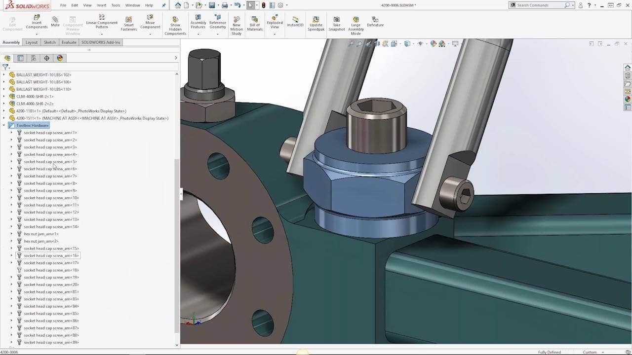
Grouping mates by status. Errors and warnings help you kind of diagnose your assembly a little bit better. Then also there is the lock rotation. If I go to my toolbox components, now if I go into my toolbox hardware, you can see my cap screws, my hex nuts and all of them have a minus sign. What does the minus sign represent? It represents underdefined. Meaning that I can still rotate.
Automatically Lock Rotation
But if I go over here, I can rotate my hex nut. If you wanted to lock the rotation for, um, just all concentric mates, if I go to my mate group, again, if I right click now there is locked concentric rotation. So I click on that, anything that has concentric, now you’ll see the before it was, you know, filled out, now it’s filled in. If I go back to my– Collapse all this and go to my toolbox hardware, you can see how we’re minus sign. Because you know a lot of those use your concentric rotation. You can do it after the fact, but say you wanted to automatically lock the rotation for your toolbox parts. There’s an option now. So going through our gear up top here, if I go into my options, let me pull this over, in my whole wizard and toolbox. We have locked rotation of new concentric mates toolbox components. If I have it checked on when I insert my toolbox parts, then it’s also kinda automatically lock the rotation when we add in the concentric mate.
Topology Study
We’ll take a look at the topology study. For validation, topology was introduced in 2018. It has support for multiple load cases and we can define it with stiffness and mass constraints. In 2019, they’ve added three more constraints: stress, a factor of safety, and frequency. And then, once we run the study, we can then save the results that we have directly to a solid mesh.
So taking a look at what a Topology study is, it’s a way to conduct non-parametric optimization of parts. In addition to stiffness and weight constraints. In 2019, I mentioned they’ve added a couple more constraints, you can see where they’ve added a frequency constraint. What this allows me to do is make sure that the design is gonna meet our vibration requirements. We can see here, for example setting a value, I can make sure it’d be less great than or in between a certain zone.
If you look here down the bottom, you’ll see the stress and a factor of safety constraint too, so, in addition, to frequency. From there, we can then compare Topology differences with the compare tool. We can do it before we added the frequency constraint and then obviously afterward and kind of double check to see which one we liked best. From there, I mentioned that you can export this food mesh to a solid mesh body. Giving us a result based on the study from our Topology study.
In addition to Topology studies, they’ve also added in a more detailed flow results visualization as well as Geometry-based setup for plastics. A lot of what we covered was more centered around SOLIDWORKS, but there are so many enhancements for all the ecosystems. We have SOLIDWORKS in the middle and then you have, PDM, simulation and all the other products in the portfolio.
One of SOLIDWORKS Drawings enhancements is the new removed section view type. So being able to kinda create a slide section really easily in a few clicks, renaming and renumbering tags in hole tables, you could do that. And then also delaying individual view updates. Then afterward, I’m gonna show you some of the bonus drawing tips that we found that sometimes people don’t know about or they kind of miss that are not specific to 2019, but just in general for SOLIDWORKS.
Popping back into SOLIDWORKS here for my drawings, open up a camera assembly and the first one that I’m gonna look at is just the section view. I want to do a slide section here from my bottom view. It’s a new section type. It’s gonna be called remove the section. And what happens is that I select, for example, the edges and their corresponding opposing edge for it. It draws in the line for us.
I can place it and then automatically create that section view. Now, I could have done that before, but it would take a few more checkboxes. Now you can jump straight into it to create that remove section. Obviously, you can always remove the alignments to say, I wanted to remove the alignment and then place it somewhere else. We can always remove that.
Adjustments for enhancements to our hole table. So if I wanted to insert a whole table here from my top view, you go to my hole table and tag order. We can set it to be X-X Y. We have reduced full-path which essentially calculates the shortest distance to connect all the holes, giving you the most efficient order from a manufacturing standpoint.
Radio Patterns
Our radio patterns just tag radio pattern from our designated origin. And then we have our tag types. We have, A, we have one, two, three, and we have manual. For example, I won’t go ahead and start to read the manual. Press okay.
Now, go ahead and place it over here. If I decided I wanted the change and the tags type just be like AA, I think it’s going to manual, type in AA, BB, it changes all of them. I can sort it by size, to combine the same sizes when it feels fit, or assign a tag prefix. For example, for C if I wanted to assign tag prefix to here, all I need to do is just right click.
Go to assign tag prefix and then select it. We’ll do it all holes of the same size or the both of these here. So there are a couple enhancements to the hole tables. And one of the last ones is delaying of individual view optic. If I were to make a change in my model, then it’s gonna automatically change the drawing too cause it’s referencing to it.
It’s backward compatible, you know, both ways. But, for example, you’re making a quite a few changes and you don’t want your drawings to always update or you want to be able to control that. There are certain views that you want, move on to like these ones here, I can exclude from automatic update. If I click on this and then press okay, say we open up that part here, and I’m gonna just make a change or make a change to the thickness on the back. We’re gonna go from seven here, to say, about 13. I’ll show you the three main views because there’s also a section B is based off those, those haven’t obviously, been updated either.
You’ll see what hasn’t been done. These other ones have been updated. For example, you know you’re done making changes and say, “Hey, you know what?” Now I wanna go and update that. You can either rebuild all of them or I just go here to click on rebuilt for the drawing or you can do it individually. For this one, I’m just gonna click on update view. What’s familiar is that that rebuild icon. You’ll see the thickness will then change. This one also changes too because it’s based on that view and then you can do them individually.
We rebuild all of them here. They keep that option turned off. So where that option was on is if I click on one here, you’ll see here it’s an exclude from an automatic update. “Well, going forward I do wanna make sure that updates, so I don’t have to always do that manual process.” Just make sure that even though you rebuilt it, it doesn’t necessarily remove that option to say exclude from the automatic update.
Going forward, if you wanted to always maintain that reference and automatically update when the part of the assembly will change, just make sure you go ahead and uncheck that. What else do we have? Some of the bonus drawing tips and, again, these aren’t specific to 2019, but just some of the things that we found has been helpful and then necessarily, people have found pretty interesting is the dimension palette. Auto-spacing dimensions, dimensioning from an angle from points and then dimensioning to a virtual sharp.
Dimension Palette
Looking at the dimension palette there are two things for it. You’ll see here that I can window select certain components and then there’s that square that pops up, that’s our dimension palette, So here you’ll see that we’re applying on multiple tolerances. I window select that icon there, right, is the dimension palette. Pulling that up, we can do a couple of things; here we’re applying, a tolerance to multiple dimensions that’s why we window select them. You can do just for one if you want it.
What else you can use in dimension palette for is arranging dimensions. So, you’ll see where they’re pretty messy. I wanna right click and or just select them and go to my dimension palette, there’s an auto-arranged dimension, for example. So I window select, click on that icon that pops up. Here, there’s auto arrange and then you kind of see them space them. They’re not locked down so you can then move them afterward and space them out even further if you like.
Sometimes people kind of wonder what that dimension palette pops up and what does it do. Those are just some of the options. Other things to is dimensioning an angle from points. Now if you had this line and you’re trying to do an angle dimension instead of drawing a construction line from necessarily from that bottom point, I’m drawing a horizontal construction line and then dimensioning from there. We can save a few clicks, or save that construction line by just simply selecting the line. So you see I go to smart dimension. Click on the line. And if I click on the point on the bottom, I get this reference like kind of x, y, z in both directions. From there, I can choose the horizontal reference for our edge. Just clicking the line, clicking on the point, and then choosing the kind of essentially that access reference that I want to use and that again my dimension.
Dimensioning Arc Angle
Dimensioning arc angle from the point, so if you dimension like a partial arc in this case, if I want to create an angle dimension, I don’t have to draw in two construction lines dimension between them. If I click on all three points, the pretty much the extent of my arc both sides as well as the-the center point, that also gets created. I can get an arch angle dimension. So going a smart dimension, center point one end of the arc, and then the other end of the arc. Virtual sharps: So say there are some edges that I’ve been filleted, but I still want to dimension to those edges, what I can do is go to dimension, right-click, find the intersection and I just simply select the two lines that I want to find the intersection too. If there’s a certain kind of orientation that you’re looking for, you can dynamically manipulate the model like this if you are opening up the model and then rotating content creating your own custom view. We can go up top here in our heads-up view toolbar, clicking on the view, then we can go and access our 3D drawing view rotated to a specific orientation that we’re looking for. And then make sure we press okay, right, to capture.
eDrawings
The last main topic is going to be eDrawings. If you use eDrawings before it allows you to review your models. So there are more file types now that are supported. We’ve also added in configurations support and then also saving as 3D HTML. Here I have eDrawings open. I mentioned the different file types so they added a couple more in here so things like Parasolid, solid edge, ACIS, JTNX, and we’re gonna open up those files too. In terms of configuration data, this is actually a fireworks file, before you’d have to save it out as like an EASM or E, ePark, specifically eDrawings file. Then you can access the configuration data, but then now you can open up the eAssembly directly and then access it.
Then obviously you still had all the functionality that we had before. And then now there’s a new function in eDrawings 2019 Pro where you can fade this and then access like a web HTML, so kind of allows you for easier collaboration. I have it open up here. Again, we still have the configuration information for us to work through. We have some exploded views in here and section views. It allows you for easier collaboration instead of necessarily looking at eDrawings, or making sure it’s installed then you can go ahead and output this to an HTML and then have them take a look at it. Also with eDrawings Viewer, which is the Windows version it now includes enable markup, measure password protection, moving components and exploded views, viewing configurations, playing SOLIDWORKS animations. Pretty much everything that was in eDrawings 2018 Pro is now available in the free Viewer. That means that going forward everything in 2019 Pro is obviously specific to Pro. One of the things would be the save to web HTML, so that’s specific to the eDrawings Pro, but everything else that we’ve kinda basically see right now is available in Pro and the Viewer.
If you want to learn more about SOLIDWORKS 2019, CONTACT US for more information!


