
The bounding box is an indispensable piece of reference geometry in SOLIDWORKS, representing the smallest area or volume in which a design can fit. While available in weldment and sheet metal models for many years, creating a bounding box for a standard part has required convoluted workarounds – until now. New in SOLIDWORKS 2018, bounding boxes can be created for standard parts with just a few clicks, enabling you to quickly find the maximum dimensions of your design and use the automatically-generated file properties as needed. To emphasize the utility of the bounding box, an organic shape will be used.
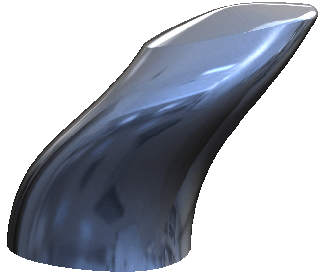
Finding the maximum extents of the design shown above would be an exceptionally difficult task without the use of a bounding box. To create one, simply navigate to Insert -> Reference Geometry -> Bounding Box in the dropdown menus. In the PropertyManager, you’ll find two methods for creating a bounding box. While both methods result in the creation of a 3D sketch and file properties, Best Fit will generate the absolute smallest box in which the design can fit, regardless of orientation, while the Custom Plane option allows for the selection of a planar element to define one of the directions of the box. Additional options allow for a preview of the bounding box, and inclusion of hidden bodies and/or surfaces.
Once created, the bounding box exists as a feature in the Design Tree, and can be edited, suppressed, or hidden like any traditional feature. As changes are made to the model, the bounding box will update parametrically while preserving the original settings, but beware when using the Custom Plane option, as model changes may result in a missing reference.
Creating a bounding box for a part also generates a number of file properties automatically, which can be linked to drawings, or otherwise used just like manually-added properties. Click File Properties in the standard toolbar, then the Configuration Specific tab to view these new properties, which include the length, width, height, and even volume of the bounding box.
It should be noted that for multibody parts, creating a bounding box using this method will include all bodies (unless hidden). As such, it’s not currently possible to create separate bounding boxes for each body individually using the new Bounding Box command. However, there are multiple workarounds available to accomplish this, including saving the bodies to discrete part files, leveraging configurations/display states to show a single body at a time, or following the established workaround for creating bounding boxes prior to 2018. Please see our video on this workaround for more information.
As seen here, SOLIDWORKS 2018 allows for the creation of a bounding box and file properties for standard parts in just a few clicks, and this capability is just one of many exciting new enhancements this year. Be sure to check out our What’s New series for additional blogs and videos on all the new features included in SOLIDWORKS 2018. For more information, check out our YouTube channel, get a SOLIDWORKS 3D CAD quote or contact us at Hawk Ridge Systems today. Thanks for reading!


