
In order to effectively set up complex studies, it is important to understand the variety of meshing options that are available in SOLIDWORKS Simulation.
General solid bodies are automatically meshed using solid tetrahedral elements, which are a great fit in a variety of cases. For geometries that happen to be constant wall thickness, there is another option that can be beneficial: shell mesh.
Shell Mesh Uses
Shell mesh can and should typically be used for a variety of geometries such as: sheet metal, PCBs, tubing/piping, formed or thermoform materials, and fiberglass/composites.
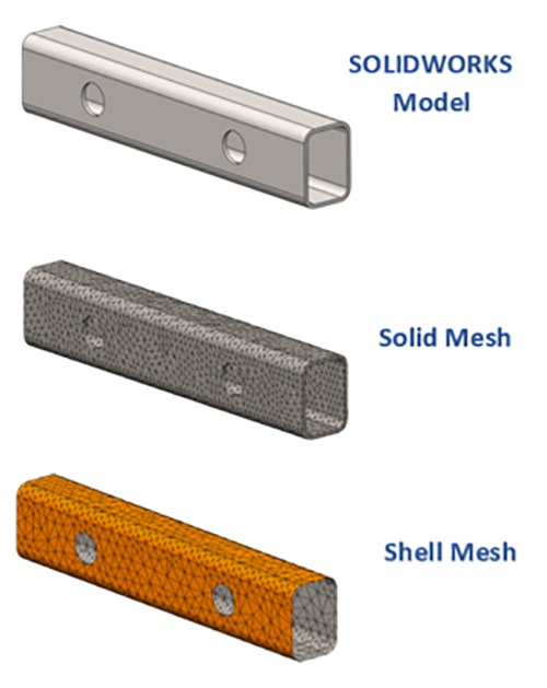
It’s quite common that we receive reports of users struggling with excessive simulation run times only to find out that they should really be using shell mesh! Solid tetrahedrals can produce an excessive number of elements on geometry that is wide/long and thin. Shell mesh avoids this issue by using 2D triangle elements, while the shell thickness is stored as a separate assigned parameter.
This greatly speeds up run time and has an added benefit of being able to quickly modify the wall thickness and re-run the study if desired.
Note: SOLIDWORKS Simulation allows mixing and matching solid, shell and beam mesh (another mesh type for long slender structural members) within a single study, so it doesn’t have to be all one or the other.
Shell Mesh Workflows
There are three workflows for creating shell mesh in SOLIDWORKS Simulation:
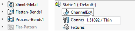
1. If the part is modeled with SOLIDWORKS Sheet Metal features, good news! The conversion to shell mesh type is automatic upon creation of the study. In this case, the thickness is also automatically assigned from the sheet metal thickness properties and is not editable from within the study.
TIP: If you are dealing with imported geometry or a sheet metal style part modeled with traditional SOLIDWORKS features, it’s worth trying the Insert Bends command from the Sheet Metal tools to convert it into what SOLIDWORKS considers a Sheet Metal part. In many cases, this will automatically produce the flat pattern of the part and enable simulation to extract the appropriate shell mesh.
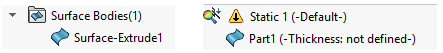
2. If the part contains any Surface Bodies, those will be automatically treated as shells within the simulation study. Since surfaces lack any thickness, the shell definition will need to be edited and the desired thickness assigned.
This means it is possible to purpose-build your CAD model for shell mesh by modeling with surfaces or converting surfaces from faces of existing solid models. This is still the preferred workflow for many users.
3. If the part contains regular Solid Bodies, the conversion process can be accomplished manually from within the simulation study.
If the wall thickness of the part is not already known, then be sure to take a moment to measure it.
Then simply right click on the part/body icon from the simulation tree and launch the command “Define Shell By Selected Faces.”
This requires selecting a continuous set of faces from either the outside or inside of the part.
TIP: A shortcut on any parts with fillets or other bends is to right click a face of the model and use the option to “Select Tangency.”
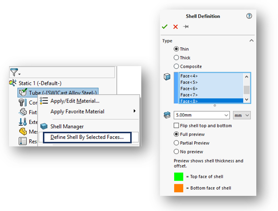
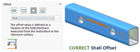
Enter the appropriate wall thickness and expand the Offset tab. I almost always use the option “Full preview” so I can see what is going on with the Shell offset. There are multiple options for Offset: midplane, top, bottom and ratio.
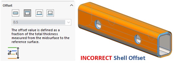
My intent here is to simply adjust the offset until the preview faces are coincident with the model. This is also a good opportunity to make sure that you have inputted the correct wall thickness.
Once these settings are adjusted click the check mark and your shell is created! When working with shell mesh, I prefer to regenerate the mesh frequently so I can visualize the mesh that is being created.
Potential Downfall
One downside of the method “Define Shell by Selected Faces” is that you will be continuing to look at the 3D solid model on the screen, while the simulation is running off of a shell mesh definition that you only see during the mesh display.
This can cause a problem – it’s very important to remember which set of faces you chose for the shell definition when it comes time to apply any loads, fixtures, contacts or mesh controls.
If you happen to make a selection from the wrong side, you should receive an error prompt such as the one below telling you to “Select entity on shell.”
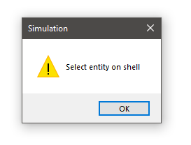
If you find yourself in this situation, simply choose from the opposite face for your selection and you should be good to go!
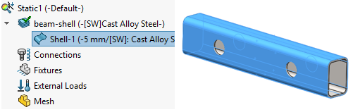
You can also expand the part icon and click on the shell definition from the simulation tree to highlight the faces that were selected for the shell definition if you need a reminder.
It might sound like there are a lot of considerations to using this method and it’s true that it takes some time to get used to, but it is by far my preferred method for defining shells. I really appreciate that it doesn’t require modifying the part model and creating extra surfaces, but still gives me the benefits of shell mesh.
For particularly complex models where you may need to mix and match many shell definitions, you should also check out the Shell Manager, which allows color coding and grouping of complex shell definitions.
Visit our site to learn more about what SOLIDWORKS Simulation can do for you, or contact us at Hawk Ridge Systems today! Thanks for reading!


