Most CAD users are familiar with the relative difficulty of modeling organic shapes and complex curvature using traditional CAD tools. While some CAD programs and reverse engineering programs have automated surfacing techniques to better deal with these geometries, they are not conducive to downstream editing. They also typically do not create perfectly prismatic features like true planar faces and cylinders. Because they are based on splines, they also have trouble defining sharp corners. This makes them often unsuitable for expressing mating surfaces, areas with mechanical function, and other key features that require perfect definition.
Additionally, these surfacing techniques tend to copy the part in its exact state along with potentially undesirable features like parting lines, logos, part numbers, imperfections and damaged areas. They don’t allow the modeler to use design intent to guide the modeling process, intuiting what the original designer intended in order to avoid reproducing the imperfections inherent in many manufacturing processes.
Oftentimes, the best solution is an approach referred to as hybrid modeling, in which traditional solid modeling is combined with automated surfacing techniques. Hybrid modeling can produce true parametric features where they are needed, while overcoming the limitations of surfacing tools, and without spending an inordinate amount of time duplicating the more difficult organic areas. We will be using Geomagic 3D Scanning software to conduct our hybrid modeling.
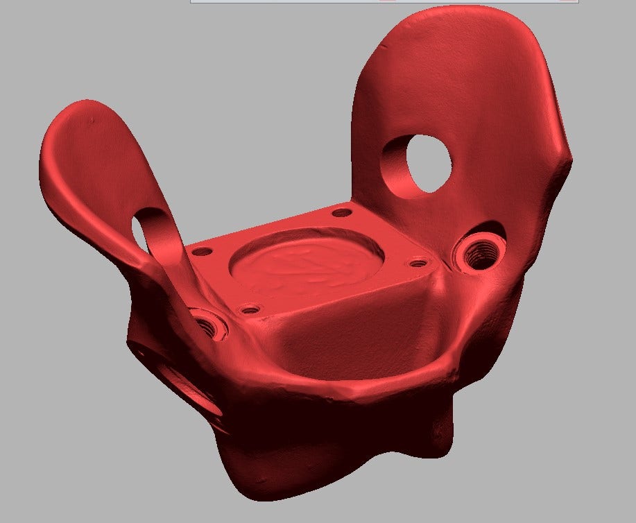
This test rig for prosthetic devices is predominantly organic in shape but has several important mating features like planes, cylinders and spherical sockets that require true CAD definition.
Make a Duplicate
After initial alignment with the world origin, the first step is to duplicate the scan data before we make any changes. We want one copy in the original state that can be used to fit CAD bodies for later cutting, and a second copy on which we will initially remove certain features that will be reproduced using the CAD bodies extracted from the first copy.
Preparing the Model for Surfacing
After hiding our reserve copy, we can proceed with removing key features, using commands like Defeature, Erase and Fill Holes. Getting rid of these areas initially will produce better surfacing results that will be easier to cut through later. In the below example, we’ve used Lasso Selection mode to select and delete the desired features, and then filled them in with the Fill Holes tool in the Polygon tab.
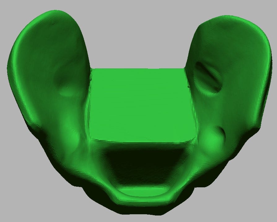
Auto-surfacing works best with a watertight (hole free) model, so here we have erased certain features and filled the remaining holes. Later, we will use proper CAD bodies to reproduce them.
Auto-Surfacing
With the model defeatured, we can proceed with surfacing it. There are various automated surfacing tools in Design X, including the Loft Wizard and the Mesh Fit tool, but in this case, we have used the auto-surface command in the Exact Surfaces tab. Auto-surfacing wraps the entire model in NURB surfaces (4-sided patches), producing a surface solid, or dumb solid.
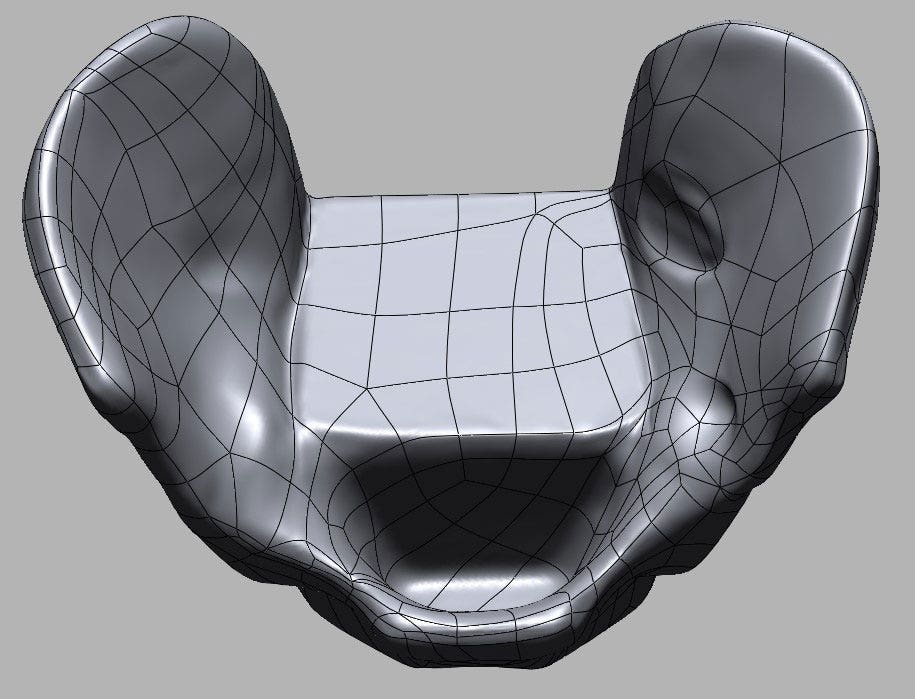
The auto-surface is complete. While surface bodies like these do not have a feature tree, they can be treated as solid bodies and used for Boolean (cutting & combining) operation.
Reproducing the Critical Features
Now that the surfacing phase is completed, we can move on to creating our critical CAD features by extracting them from the first unedited scan.
Auto-Segmenting
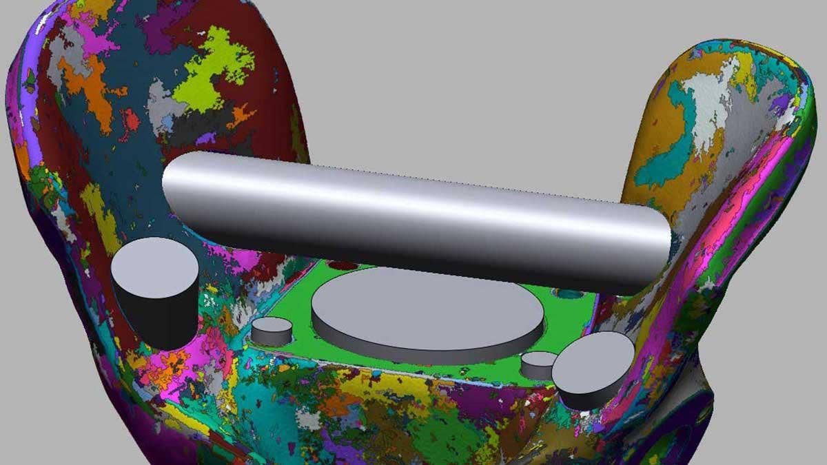
We begin the process by un-hiding the first unedited mesh and running the Auto-Segment command in the Home tab. Auto-segmenting is a type of feature recognition that can analyze the scan data and identify standard features like cylinders, cones, planes, etc., dividing them into distinct regions denoted by randomly assigned colors. These regions can now be used in various ways to drive the modeling process. While these regions work contextually with many of the tools and wizards in Design X, in this case we have used the Solid Primitive tool in the Model tab.
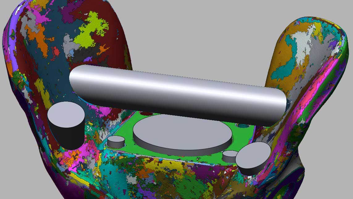
This mesh has been auto-segmented into colored regions and the cylinders have been automatically fitted to the scan data by selecting a colored region and extracting them with the Solid Primitive option.
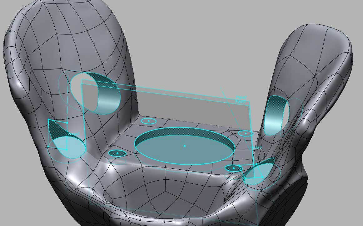
Inserting Solid Features
Using the Solid Primitive option, we can define what type of feature we want to extract and select the region(s) we want to use for the extraction for each feature. In addition to inserting these basic shapes, we can also use region groups to define sketch planes and cutting planes for more advanced modeling. After extracting all the critical features, we can now un-hide the auto-surfaced model and begin cutting into it with the features we’ve extracted.
The auto-surfaced ‘target’ body cut by the inserted “tool” bodies.
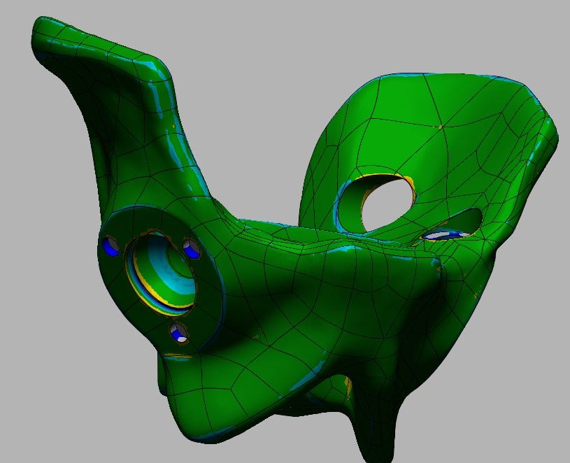
After cutting more sections removed using the same method, we have run the accuracy analyzer to make sure the resultant model conforms closely to the scan data.
As a final step, we can use the accuracy analyzer to confirm the accuracy of the model we’ve created. The hybrid model can now be exported as one of many available file types, or live transferred into a CAD program.
Interested in Geomagic pricing? If you have any questions, contact us at Hawk Ridge Systems today. Thanks for reading!


