Welcome to my second article in this series on using TolAnalyst for
assemblies. In this second article, I’m going to set up a tolerance analysis
so that you can see what’s involved. Before going any further, if you haven’t
done so already,
please read Part 1 of this series. Go ahead, I’ll wait…
Okay, now that’s out of the way, let’s go back into this “sheeter” assembly.
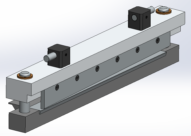
All of my parts have DimXpert dimensions and tolerances, so I can start my
TolAnalyst study to make sure the knives don’t bind together and aren’t too
far apart. In this case, over ¼” apart would be too far because the assembly
won’t cut a sheet at that point.
There is a 4 part process to our study:
- Define the measurement you want to control.
- Define the assembly sequence.
- Define the assembly constraints.
- Run the analysis and adjust the tolerances as necessary.
This article will cover Steps 1 through 3, and the last article in the series
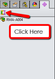
will cover running the analysis and refining the results. To start the study,
click on the DimXpert Manager tab and click the TolAnalyst icon. (Remember, if
this isn’t available, make sure that TolAnalyst is turned on as an Add-in.)
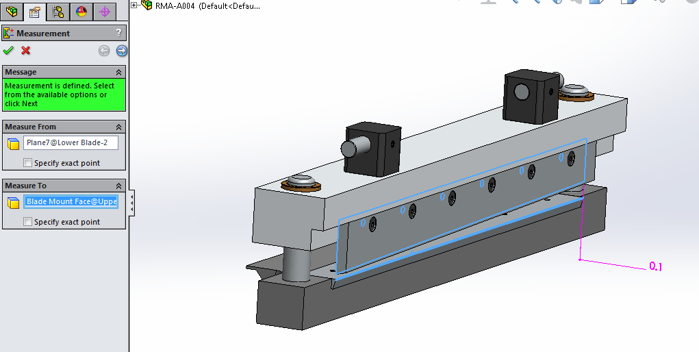
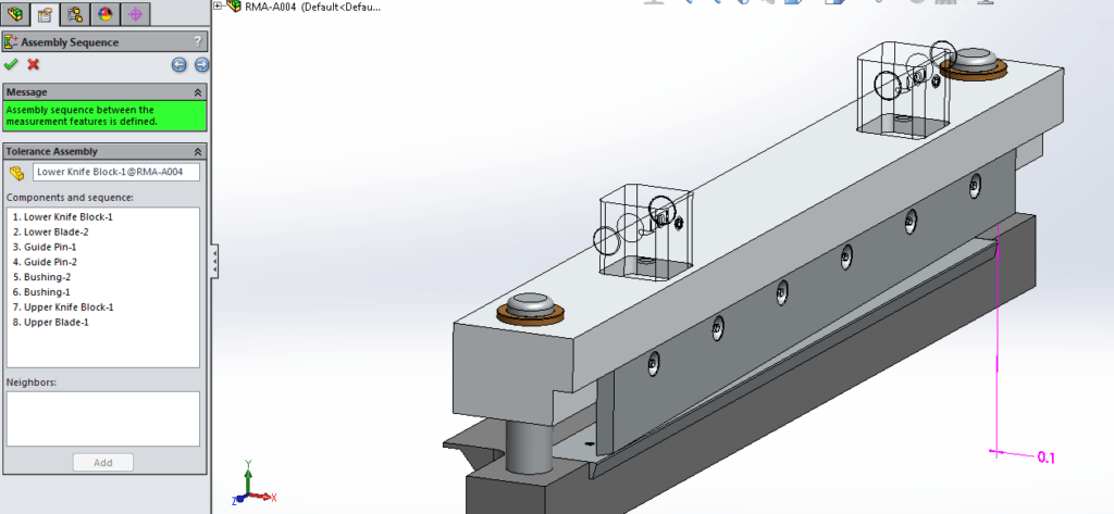
In the Property Manager, pick the 2 faces that you want to set up as
measurement faces. The measurement is the dimension that you are running the
analysis for. In this case, it’s the distance between the front face of the
bottom knife and the back face of the top knife. The nominal dimension is 0.1”
and is highlighted in pink. SOLIDWORKS also gives us a green message letting
us know the measurement is defined. Hit the blue arrow to the top right to go
to the next step.

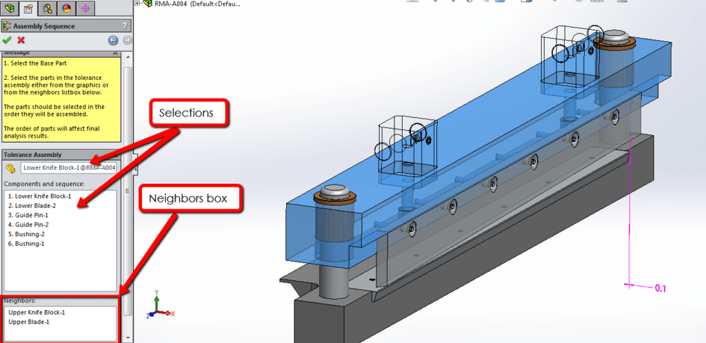
Step 2 is telling TolAnalyst the order/sequence of how the assembly goes
together. Mimicking the real world assembly sequence, it will be as follows:
the lower knife block, the lower blade, the 2 guide pins, the 2 bushings, the
upper knife block and finally, the upper knife. Just select the parts in the
proper order, and you can right click on a part and delete it if it’s out of
sequence. While you are selecting, the rest of the parts in the assembly
remain transparent until they are selected. SOLIDWORKS also provides you with
a “Neighbors” box which you can use to select parts next to the one you are
selecting, or you can select them from the graphics area.
Once you have selected everything, you get the nice green message. Hit the
right blue arrow to go to the next step.
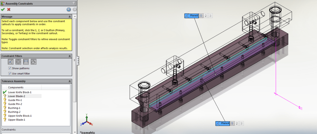
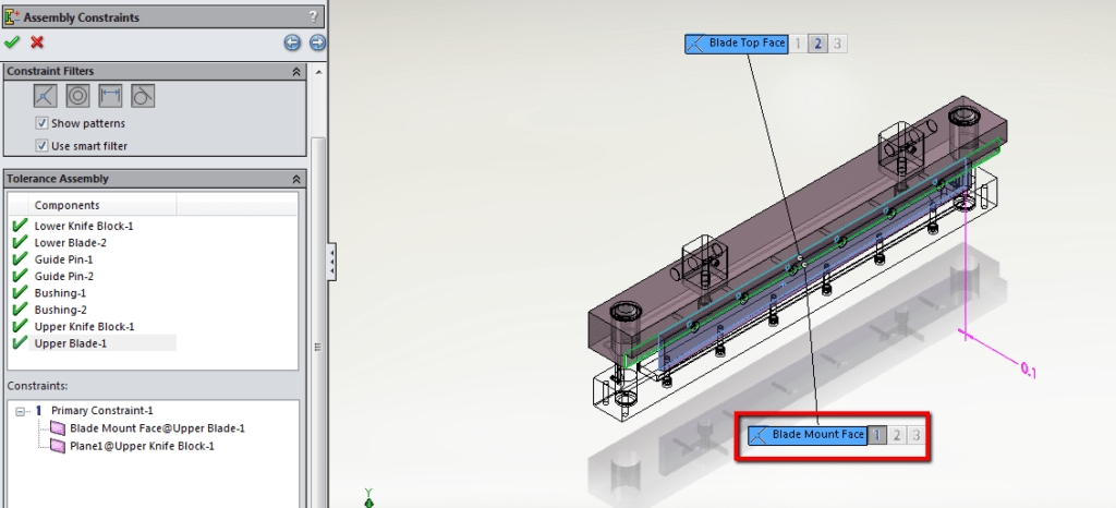
Step 3 is defining the constraints in the assembly. TolAnalyst looks at the
mates within the assembly for these constraints, which will define how the
components are held together. Pick from all the available mates to specify
primary, secondary and tertiary constraints depending on real world
conditions. The first component is the lower knife block, which is fixed due
to it being the first component in the sequence from the previous step, so we
need to set up the constraints for the next component, which is the lower
knife blade. You can see from the image, there are 2 mates to pick from, one
on the bottom of the blade and one on the back of the blade:
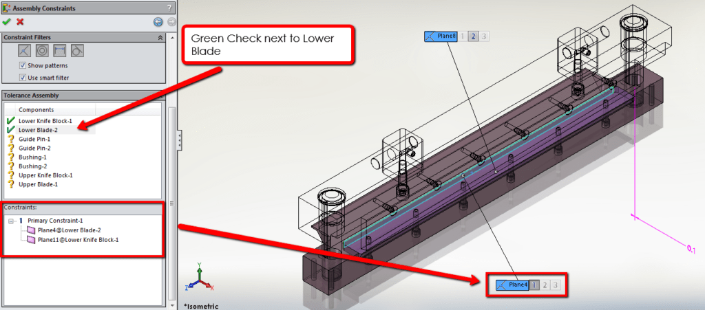
You can pick both of these constraints, but you really only need to constrain
the blade in the X (red axis) direction, since the blade moving up and down in
the Y direction won’t affect the tolerance stack up. If you hover over the
flyouts, the faces that are being covered by that constraint highlight in
green. Once you pick 1 or more constraints, the Component in the Property
Manager has a green check next to it. Also, under that Components window, the
Constraints window shows the primary, secondary and tertiary constraints and
what faces they are between.
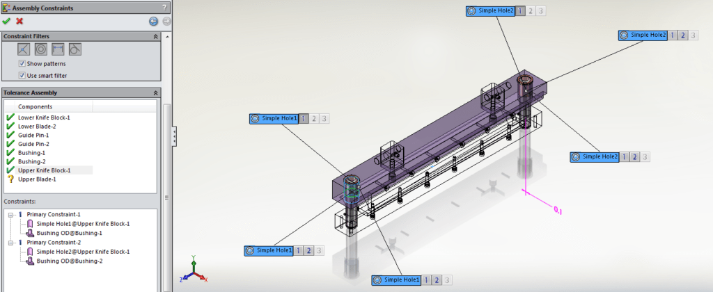
After that, it’s just a matter of selecting the constraints for the other
components. Click on the component, see what constraint or constraints pop up
in the Graphics Area, and then select the number on the flyout. 1=primary,
2=secondary, and 3=tertiary. You can specify the constraint filters that you
want to use, or just let SOLIDWORKS show all and pick from there. Everything
in this assembly is pretty straight forward until you get to the Upper Knife
Block. It has 6 possible constraints to choose from. This is where the green
highlighting becomes key, so that we can pick the constraints between the OD
of the bushing and the block (confirmed by the Constraints box).
Just one last part to select, and that is the upper blade and its mount face.
Next, I just have to hit the Next arrow again to run the study… and that’s
where I’ll end this article (cliffhanger!)

Stay tuned for Part 3, and if you prefer, you can see my
YouTube video here. Thanks for reading!


